


DC 12V PWM Fan Hız Kontrol Devresi
PC CPU Soğutucu Fan Alarm STK IC için 4 Telli Bilgisayar Sıcaklık kontrol Anahtarı
Modül sadece dört pin standart pwm destekli fanların hızını kontrol eder. Fanı kapatmaz. Doğru sıcaklık ayarı ve hassas kontrol ile tam dijital kontrol yapar. Manuel hız regülasyonu ve otomatik sıcaklık kontrolü ve hız düzenleme işlevini birleştirir. Manuel hız kontrolü %10 ile %100 arasında yapılabilir, her %5’lik artış bir kademedir. Otomatik sıcaklık kontrollü hız ayarı 30C den itibaren başlar, 49 farklı sıcaklık bölgesi kombinasyonu vardır. Üç hatlıdan dört hatlıya kontrolleri destekler ve ayarlanan parametreleri otomatik olarak kaydeder.
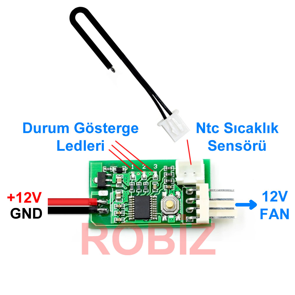
Giriş hattı: Kırmızı-siyah güç kablosu yalnızca 12V pozitif ve negatif güç kablosunu lehimlemek içindir ve genel kullanım amaçlıdır. Üç telli konnektör, bazı anakartların üç telli fan portlarının hızını ölçmek için kullanılan 2510-3P fişle donatılmıştır. Büyük 4P arayüz, kasadan kolayca güç almayı sağlar.
Sıcaklık probu: İnce siyah kablonun ucu kısa ve düşük ısı kapasitelidir. Dar alanlarda ve hava sıcaklığı ölçümlerinde kullanılmaya uygundur, tepkime süresi oldukça hızlıdır. Halka tipi prob, çapı 4.2 mm olan halka şeklindeki metal başlık içine yerleştirilmiştir. Radyatör veya başka bir ısı kaynağının yüzeyine sabitlenerek kullanıma uygundur.
Özellikler:
- Çalışma sıcaklığı: -10C / 60C
- Çalışma voltajı: DC 12V ( 8V / 18V )
- Çalışma akımı: 20mA
- Fan akımı: 3A den az olmalıdır
- Hız aralığı: %10 - %100
- Mod kontrol butonu
- 3 Adet durum gösterge ledi
- Sensör: NTC 50K B=3950
- Boyutlar: 34mm*19mm*11mm
- Ağırlık: 5gr.
Varsayılan fabrika değerleri: Düşük hız 20%, Hızlanma sıcaklığı 30C, Hızlanma genişliği 5C. Bu sıcaklık ayarının altında, termal probunu elinizin avuç içi ile tutmak bir süre sonra hızlanır ve prob koltuk altına sıkıştırılırsa, genellikle 2 dakika içinde tam hıza ulaşacaktır.
Otomatik Kontrol:
3 parametre ayarlanabilir:
- Po: Başlangıç hızı
- Tu: Fan devrinin artmaya başladığı sıcaklık
- TD: Devir sayısının maksimuma ulaştığı sıcaklık farkı
Po değeri, cihaz açıldıktan sonra ayarlanır. Aşağıya çift tıklama, yukarıya tek tıklama ile değiştirilir. 1 + 2 düğmelerine basılı tutmak minimum, 2 + 3 düğmelerine basılı tutmak maksimum devire ulaşır. Tu’yu ayarlamak için 3 saniye basılı tutulur, yavaşça yanıp sönmeye başlar. Değeri girmek için bir kez daha tıklanır ve değer tabloya girilir. 3 saniye daha basılı tutulduğunda hızlı yanıp sönmeye başlar, bu da TD'nin ayarlanmasına olanak tanır.
1>. Sıcaklık probu olmadan manuel kontrol:
Butona tek veya çift tıklama ile hız kademesi yukarı/aşağı ayarlanır (çift tıklama çok hızlı olmamalıdır). Her değişiklikten sonra 20 saniye içinde hız kademesi otomatik olarak kaydedilir. No. 2 gösterge ışığı 20 saniye boyunca hızlı yanıp söner (sıcaklık kontrolü devre dışı olduğunda). Yanıp sönme durduğunda dosyanın kaydedildiği anlamına gelir. 3 / 1 gösterge ışığı, mevcut kademe artırılamadığında / azaltılamadığında sürekli yanar.
2>. Sıcaklık probu takıldığında:
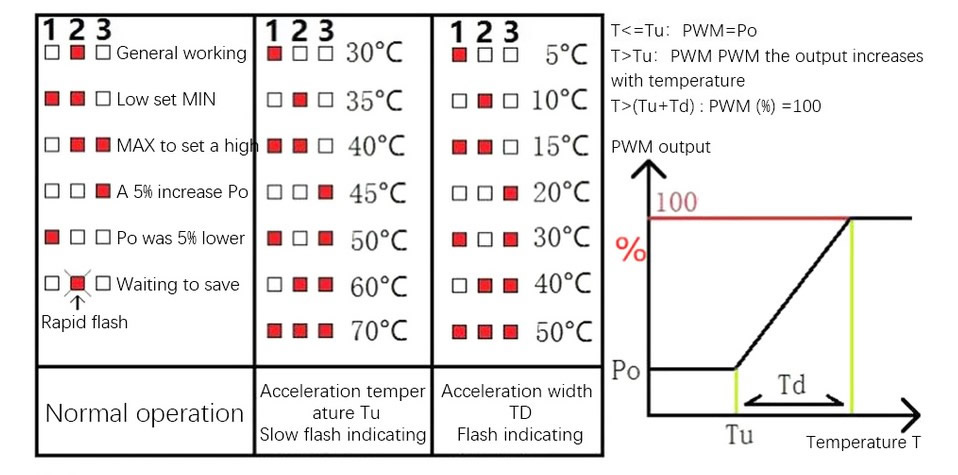
Manuel ayarlanan hız, başlangıç (alt sınır) hızı olarak kullanılır. Sıcaklık, hızlanma sıcaklığını aştığında, fan hızı sıcaklıkla orantılı olarak artar. Sıcaklık, hızlanma sıcaklığı + hızlanma genişliği toplamına ulaştığında veya geçtiğinde fan tam hızda çalışır.
Hızlanma sıcaklığı ve hızlanma genişliği parametreleri, aşağıdaki şematik diyagramda gösterildiği gibi ayarlanır. 123 numaraları, kart üzerindeki gösterge ışıklarını (kırmızı) ve (beyaz) durumu ikili (binary) düzende temsil eder.
Paket içeriği:
- 1 Adet 12V Fan Hız Kontrol Devresi