- Stok Durumu: Stok Var
- Marka: OEM
- SKU: RBZ.101.606
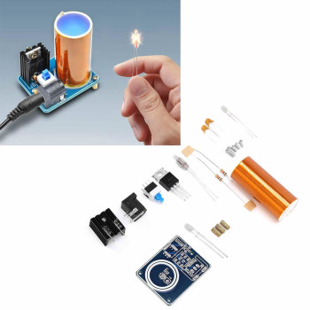
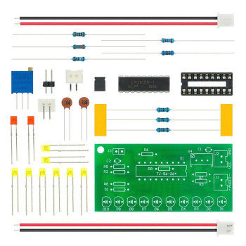
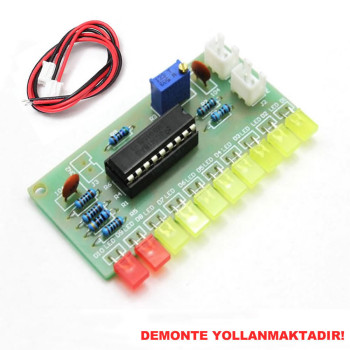
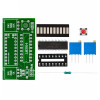
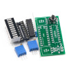
Disassembled LM3914 10 Led 3.7V Lithium 12V Battery Capacity Indicator Module
DIY Led Electronic Soldering Training Circuit
The product is in disassembled state. The soldering process causes physical change. The soldering process prevents return.
For disassembled products, there is no operating guarantee of the circuit.
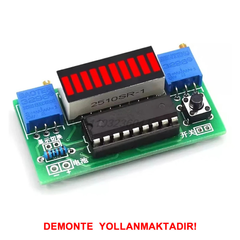
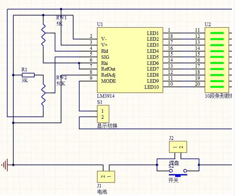
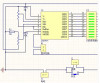
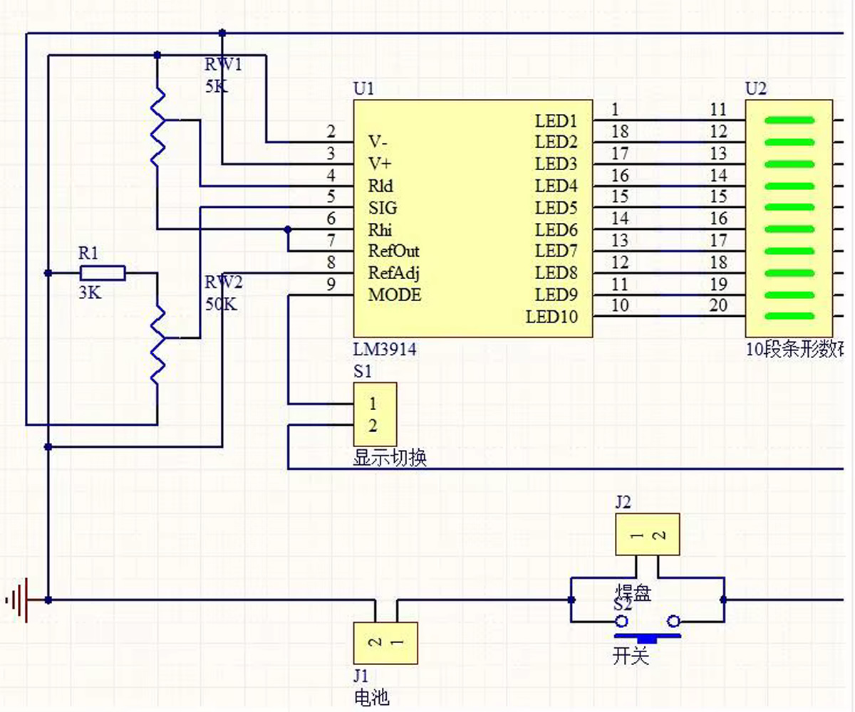
This disassembled module visually displays the analog voltage level as a 10 led bar graph using the popular LM3914 integrated circuit. Thanks to the operating system with a voltage range adjustable by potentiometer, it easily adapts to different batteries. It detects the battery voltage precisely and displays it over 10 leds.
Display mode description: The voltage between the upper and lower limits of the battery is divided into 10 levels. Each led represents 10% of the power indication. Thus, the power range of the battery from 0% to 100% is clearly observed with 10 leds. In addition, a single led display mode with a changeable mode is also available. In this mode only a single led lights up and this consumes less power. While one led consumes 4mA, the total consumption is 42mA when all leds are lit.
The main purpose of the kit is to recognize electronic components, to learn the structure of electronics and circuits, and soldering training processes. Students can create the circuit very easily and quickly with fewer errors. It considerably shortens the soldering training process. Easy creation of the electronic circuit makes it easier to learn and love electronics. Soldering starts with the lowest profile, that is, the smallest components. Then it is necessary to gradually move on to soldering larger components. The numbers and names of the components are written on the pcb. The correct places of the components are found easily.
Application:
- It is suitable for lithium batteries, lead-acid batteries and other batteries requiring a power indicator.
- The display range of the power supply is adjustable; the battery discharge curve is scientifically set.
- Directly supported battery types:
- Single cell lithium: (4.2V) - 4 cell lithium: (16.8V)
- Lead-acid: 6V - 12V
- Nickel hydrogen: 3.6V - 18V
- Nickel cadmium: 3.6V - 18V
Example led operating arrangement: For example, when 1 piece of 3.7V lithium battery is used, the full charge state is set as 4.2V.
- 4.2V Display: (all of the leds light up)
- 3.7V Display: (a certain part of the leds light up)
- 3.0V Display: (Only the first led lights up)
Features:
- LM3914 Disassembled Kit
- Operating voltage: DC 5V / 18V
- Operating current: 40mA
- Measurement range: generally battery DC 3V / 20V
- 10 bar led indicator
- Quality pcb
- High and low voltage level adjustment pots
- Mode selection button
- Operating temperature: -10C / +65C
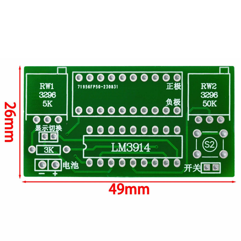
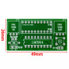
- Dimensions: 26mm x 49mm
- Weight: 13gr
Adjustment tables according to battery types:
Lithium batteries:
- A single lithium battery is 3V when discharged and 4.2V when fully charged.
- 1 section: 3V (first led) - 4.2V (tenth led)
- 2 sections: 6V - 8.4V
- 3 sections: 9V - 12.6V
- 4 sections: 12V - 16.8V
- Other series voltages can be calculated similarly.
Lead-acid batteries:
- Generally 6V or 12V batteries are used.
- For 6V: 4.8V (first red LED) - 6.75V (tenth led)
- For 12V: 9.6V (first red LED) - 13.5V (tenth led)
- This module is designed according to the standard battery discharge ranges above and accurately reflects the battery power, allowing users to observe the battery status at any time.
Adjustment: For example, for single cell lithium 3.7V: 3V is accepted as the low capacity limit; 4.2V as the full capacity limit.
- Set the adjustable power supply to 4.2V, which is the required high display voltage. Connect it to this board. At this stage two situations are observed: the leds either light up weakly or all of the leds light up. Slowly adjust the 503 (50k) potentiometer on the board. Complete the adjustment when all leds start to light up. If the leds are lighting up weakly or are too bright, slowly adjust the potentiometer counterclockwise or clockwise.
- Set the power supply to the low battery voltage 3V. By adjusting the 502 (5K) potentiometer on the board, make only one led light up. If the led does not light up, adjust the potentiometer clockwise, if a few or all of the leds light up, adjust it counterclockwise.
- Patiently repeat the first and second steps. Generally the desired display range is reached when the adjustment is made twice.
- If you do not have a precise voltage source, you can use fully charged and empty batteries for the adjustment.
Package contents:
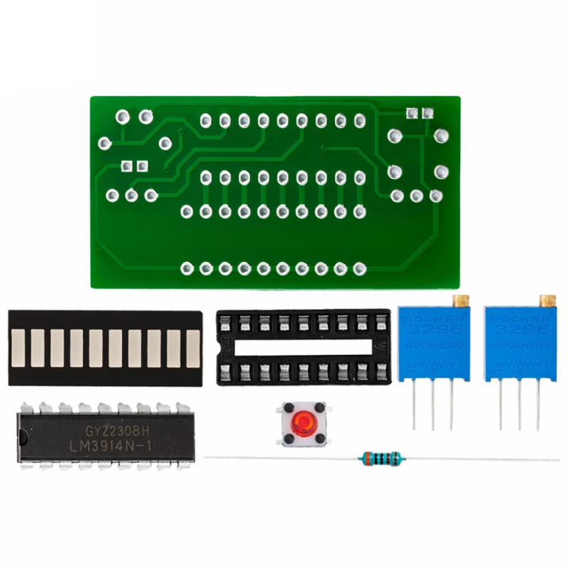
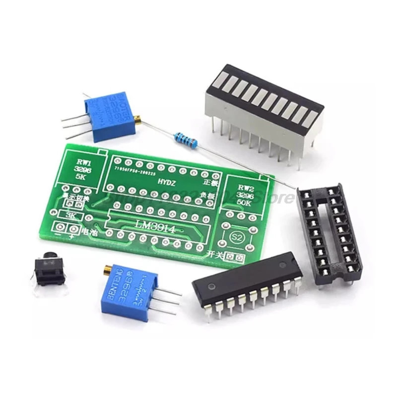
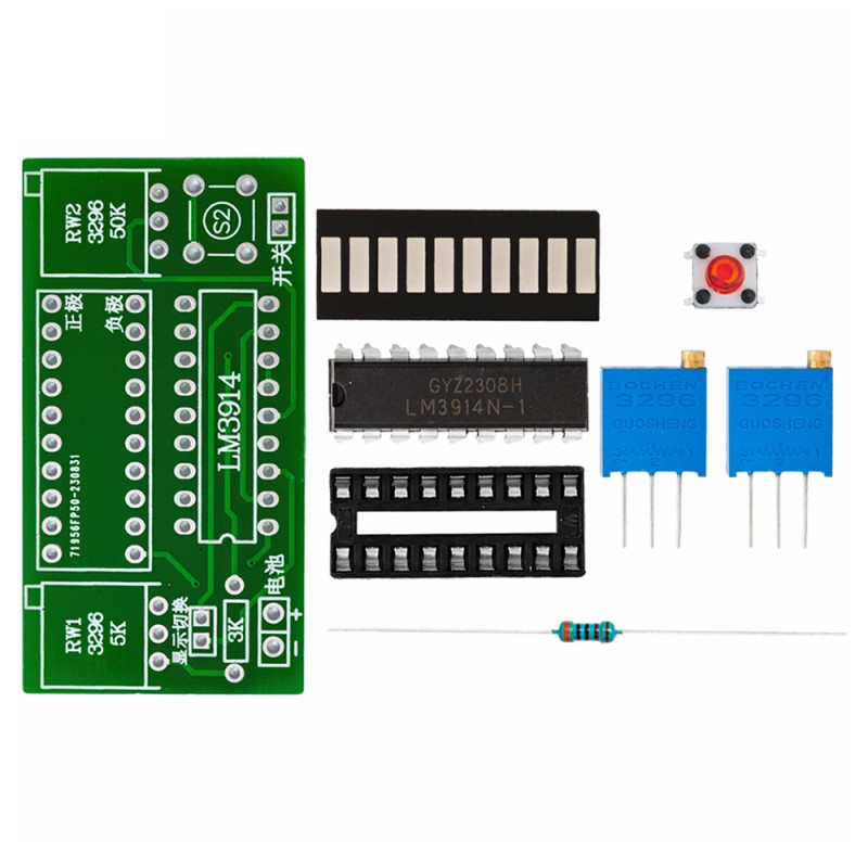
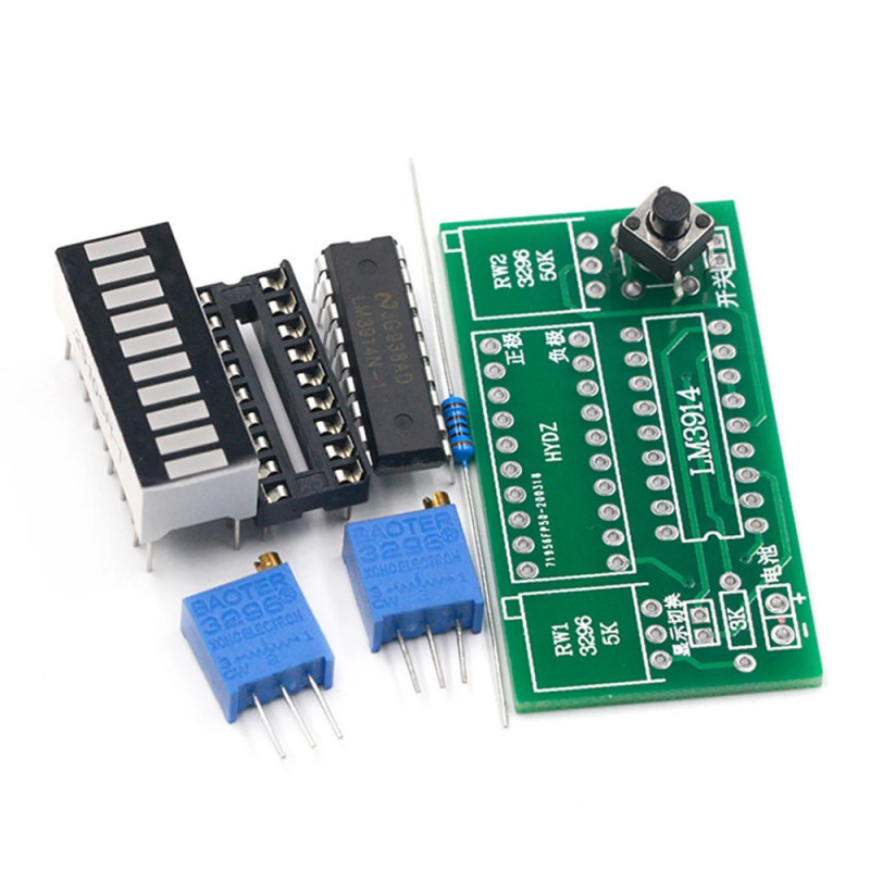
- 1 piece LM3914 and integrated circuit socket
- 10 bar led
- 2 pieces potentiometer ( 5kohm and 50kohm )
- 1 piece 6x6 button
- 1 piece 3kohm resistor
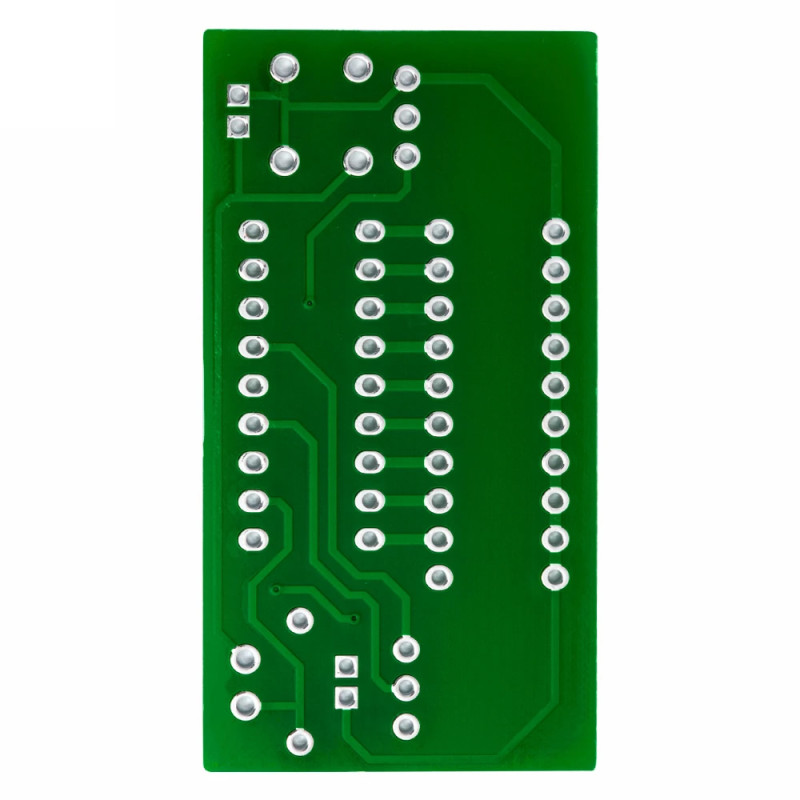
- 1 piece pcb
Adjustment tables according to battery types:
Lithium batteries:
- A single lithium battery is 3V when discharged and 4.2V when fully charged.
- 1 section: 3V (first led) - 4.2V (tenth led)
- 2 sections: 6V - 8.4V
- 3 sections: 9V - 12.6V
- 4 sections: 12V - 16.8V
- Other series voltages can be calculated similarly.
Lead-acid batteries:
- Generally 6V or 12V batteries are used.
- For 6V: 4.8V (first red LED) - 6.75V (tenth led)
- For 12V: 9.6V (first red LED) - 13.5V (tenth led)
- This module is designed according to the standard battery discharge ranges above and accurately reflects the battery power, allowing users to observe the battery status at any time.
Adjustment: For example, for single cell lithium 3.7V: 3V is accepted as the low capacity limit; 4.2V as the full capacity limit.
- Set the adjustable power supply to 4.2V, which is the required high display voltage. Connect it to this board. At this stage two situations are observed: the leds either light up weakly or all of the leds light up. Slowly adjust the 503 (50k) potentiometer on the board. Complete the adjustment when all leds start to light up. If the leds are lighting up weakly or are too bright, slowly adjust the potentiometer counterclockwise or clockwise.
- Set the power supply to the low battery voltage 3V. By adjusting the 502 (5K) potentiometer on the board, make only one led light up. If the led does not light up, adjust the potentiometer clockwise, if a few or all of the leds light up, adjust it counterclockwise.
- Patiently repeat the first and second steps. Generally the desired display range is reached when the adjustment is made twice.
- If you do not have a precise voltage source, you can use fully charged and empty batteries for the adjustment.
Package contents:
- 1 piece LM3914 and integrated circuit socket
- 10 bar led
- 2 pieces potentiometer ( 5kohm and 50kohm )
- 1 piece 6x6 button
- 1 piece 3kohm resistor
- 1 piece pcb
.