- Stok Durumu: Stok Var
- Marka: OEM
- SKU: RBZ.101.795
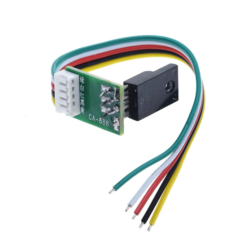
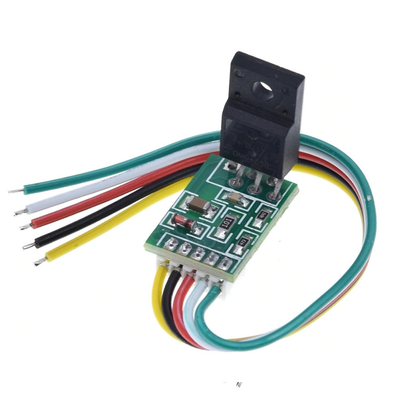
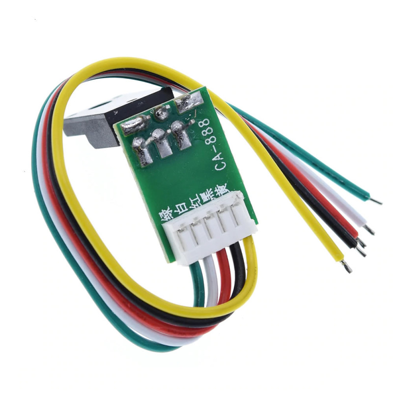
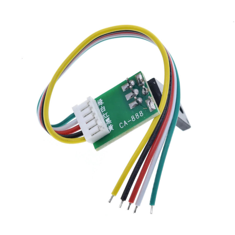
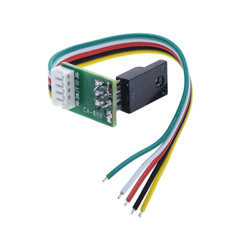
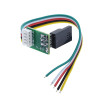
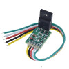
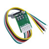
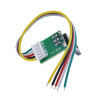
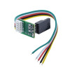
DMO465R Lcd Power Supply Control Board
Tv Television 15-24 inch Monitor 300V to 12/18V Smps Repair Circuit Universal Power Module
The DMO465R module is used in the power stage of Lcds. In faulty circuits it enables the output voltages to be generated by driving the transformer. It is used to reduce the 300V input voltage to the 12-18V level.
There are videos related to the installation of this board on Youtube. Persons performing this operation, which involves high voltage, must have knowledge about this type of circuit. In case of incorrect operations it may create a danger to life or the related circuits may be damaged. This matter is under the responsibility of the buyer.
Features:
- Model: DMO465R
- Lcd tv power supply control board
- Input voltage: 300Volt
- Output voltage: 12/18 Volt
- Compatible tv sizes: 15 - 24 inch
- Area of use: Lcd Tv monitor
- Quality, long lasting use
- Operating temperature: -40C / 80C
- Cable length: 10cm
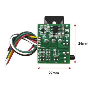
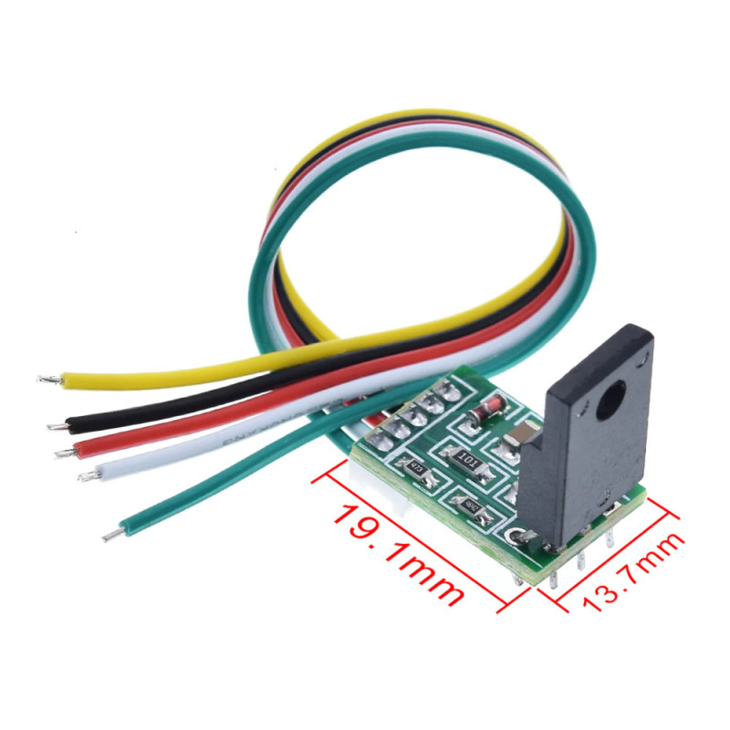
- Product size: 13.7mm x 19.1mm
- Weight: 5.5gr
Package contents:
- 1 Piece DMO465R power module
DMO465R is used to solve the power supply repair problems of 15/24 inch LCD monitors. On Lcd tv power boards, power, chip, high power switch and sampling resistor problems are largely seen. Due to the variety of these component models, mostly the same spare part cannot be found and it cannot be repaired. The advantages of this module; the simplicity of the wiring, its easy installation, providing time saving, increasing the maintenance success rate etc. bring up the idea of developing a universal power supply module for users experiencing maintenance problems.
Instructions and Checks:
- Removing the power supply chip and the switches: Remove the power supply chip and the switches (MOS tube) on the circuit board.
- Capacitor check: Check the 300V capacitor and the capacitance at the last part of the package; if there is no drum (coil), evaluate whether there is a problem at the first replacement.
- Circuit final check: Check the last page; make sure that there is no short circuit, advertisement board or high voltage board.
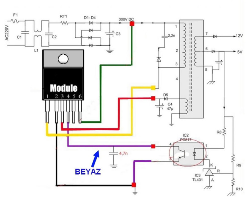
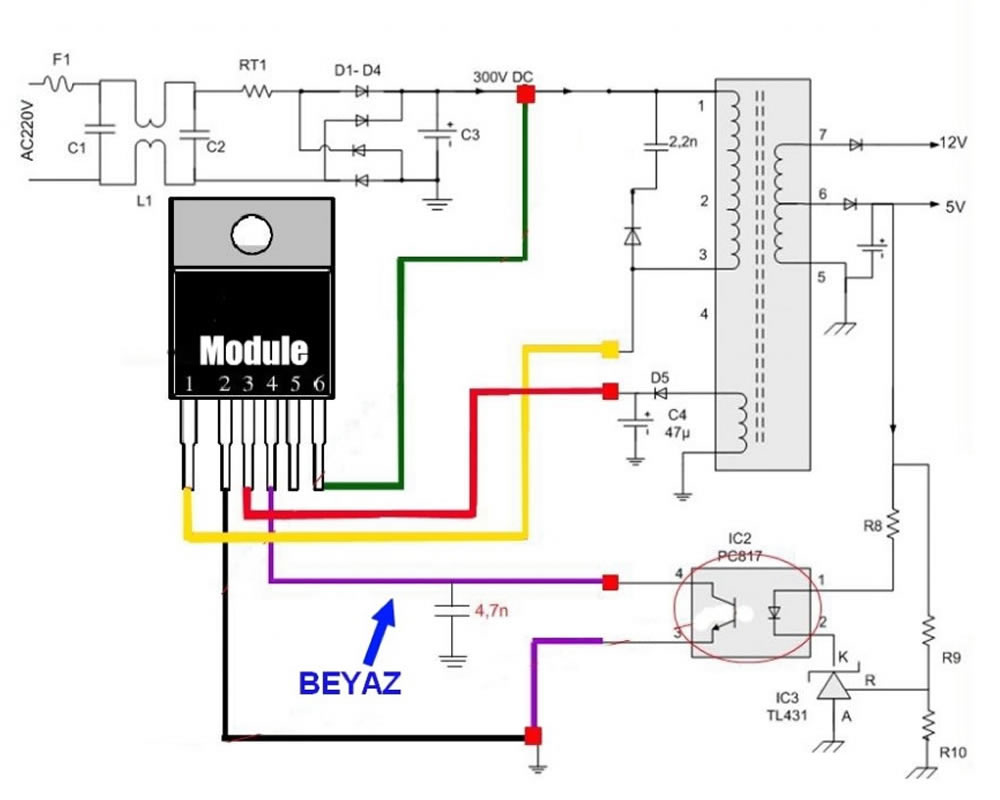
- Connection process: Connect the module to the relevant line and carefully make sure that there is no wrong connection; in case of wrong connection the module may explode.
- Assembly: Mount the module in the original place of the radiator; provide insulation and short circuit protection.
- Power and voltage measurement: After power is applied, check the performance of the measured voltage. If there is no problem, check the second cause, that is, the pin connections.
Cable description:
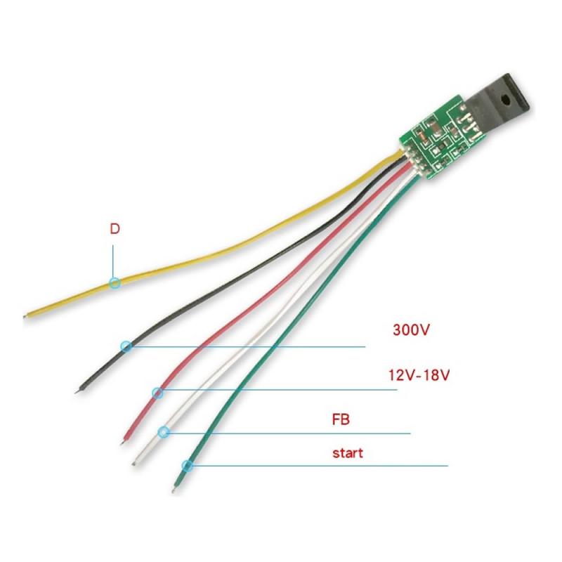
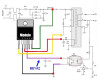
- Yellow: Drain pin, power control side; the D (polarity) end of the original high power MOS power supply. It is usually located in the middle of the power switch tube.
- Black: GND, module ground (300V); then the negative capacitor is connected directly to a large filter capacitor on the same line.
- Red: VCC, module power supply; then the rectifier capacitor at the feedback winding terminal is connected to the positive side. Continuous power supply is provided; the voltage tolerance is approximately in the 12% - 18% range.
- White: FB (voltage feedback); it is connected to the 4 pin optocoupler. Please check the heating of the 3rd pin of the optocouplers; if there is heating, the optocouplers must be evaluated separately from the hot ground connection.
- Green: Start-up pin; then comes the positive terminal of the +300V capacitor.
Can Be Replaced With the Following Parts
- 203D6.230D6 NCP1203D60R2G 203X6
- LD7552BN LD7575SI LD7575GS LD7575 LD LD575 LD7575
- OB2268.OB2269
- 3842.3843.3844.3845
- EA1530.EA1532 TEA1507 TEA1522
- DAP8A DAP08
- 1200AP40 1200AP60 1200AP100 1203P60 1203P100
- FAN7601.FAN7530 FA5511 FAN6961 FA5500
- L6562D.DM0365R 5H0165R DM0365R 0665 0265
- NCP1271 NCP1270 NCP1653
- 2AS01.2BS01 FSQ100