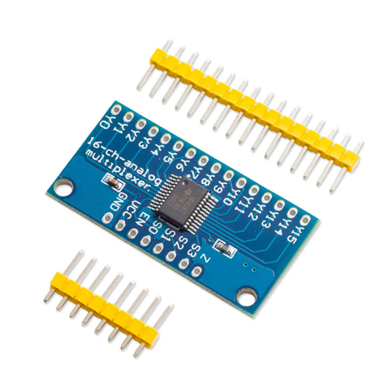
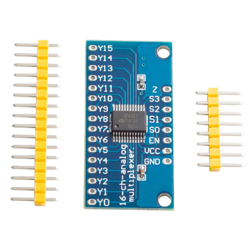
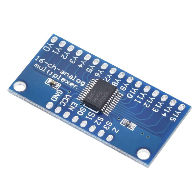
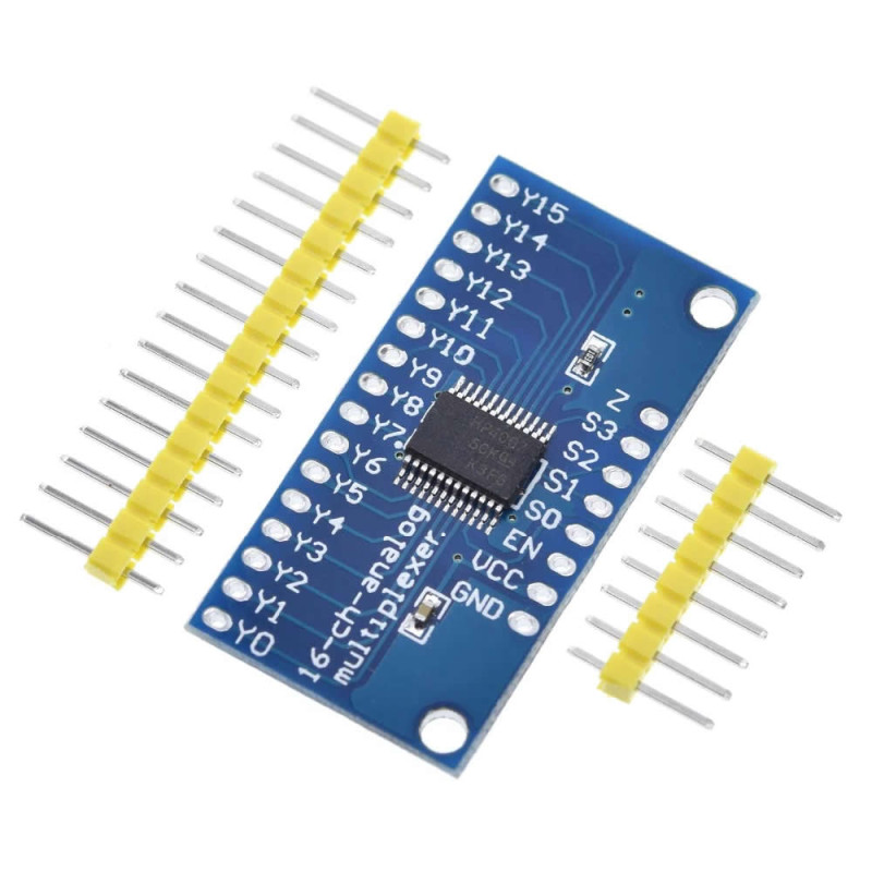
- Stok Durumu: Stok Var
- Marka: OEM
- SKU: RBZ.100.321
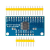
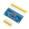
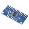
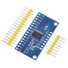
CD74HC4067 16 Channel Analog / Digital Multiplexer and Selector Module
Demultiplexer Mux Selector Pin Expander Sensor Reading Potentiometer Button Keypad MIDI Controller Soil Moisture LDR Greenhouse NTC Line Follower
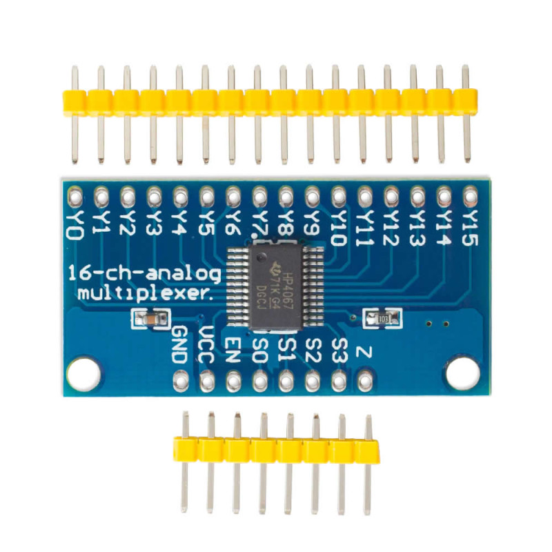
The CD74HC4067 module is a 16 channel analog / digital multiplexer board that connects a single common pin (Z) to one of 16 channel pins (Y0 - Y15). The channel is selected by a 4-bit binary address applied to the S0 - S3 address pins on the board; so with only 5 pins of the control board (4 address + Z) 16 signals can be read, or a single signal can be routed to one of 16 points. The board operates between 2V and 6V and is used with 3.3V and 5V systems.
The switches inside the chip are bidirectional and pass both analog and digital signals: as a multiplexer it connects 16 sensors to a single analog input, as a selector (demultiplexer) it connects a single output to 16 points. The channel on resistance is about 70Ω at a 4.5V supply, and each channel passes at most 25mA. Switching is break-before-make; while the channel changes, two channels are never shorted together. When the EN pin is set HIGH, all channels are disconnected.
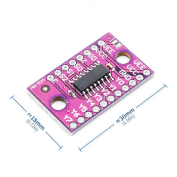
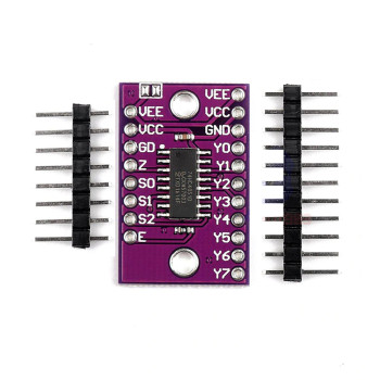
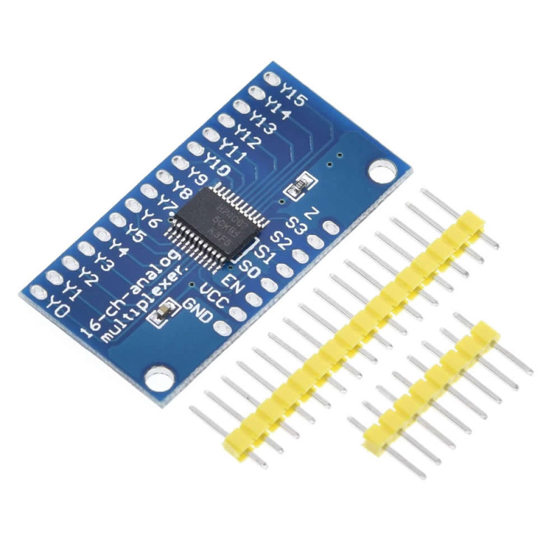
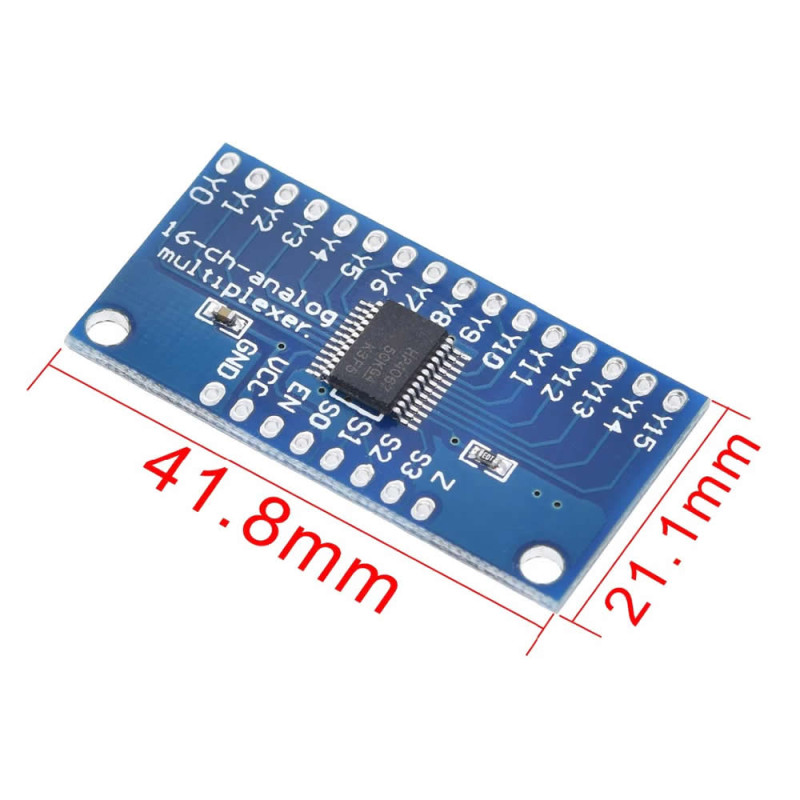
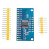
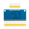
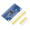
The pins are labeled Y0 - Y15 and GND, VCC, EN, S0, S1, S2, S3, Z along the two long edges of the board; the 16 and 8 pin male headers in the package are soldered into the 2.54mm pitch holes and the board is plugged into a breadboard. It suits potentiometer panels and setups that read many sensors and buttons.
Key features:
16 channels with 5 pins: 16 channels are accessed with 4 address pins (S0 - S3) and the common Z pin; 16 sensors are read in turn with a single analog input of the control board.
Analog and digital, bidirectional: The channels pass any voltage between GND and VCC in both directions; the same board is used as a multiplexer to read sensors and as a selector to distribute a signal.
Wide supply range: It operates between 2V and 6V; when powered from the logic voltage of the control board (3.3V or 5V), no level shifter is needed.
Low on resistance, safe switching: Thanks to about 70Ω on resistance at 4.5V and break-before-make switching, neighbouring channels are not connected together while the channel changes.
Disable all with EN: When the EN pin is set HIGH, all 16 channels are disconnected; several boards can share the same Z line to expand to 32 or more channels.
Features:
- Product type: 16 channel analog / digital multiplexer / demultiplexer module
- Chip: CD74HC4067, single common pin 16-way analog switch
- Number of channels: 16 (Y0 - Y15), common pin Z (SIG)
- Channel selection: 4 address pins S0, S1, S2, S3 (binary address 0 - 15)
- Enable (EN): while LOW the selected channel is connected, while HIGH all channels are disconnected
- Operating voltage: 2V - 6V (compatible with 3.3V and 5V systems)
- Signal type: analog and digital, bidirectional; signal voltage between GND and VCC
- Channel on resistance: about 70Ω at 4.5V
- Channel current: 25mA maximum
- Switching: break-before-make, about 6ns at 4.5V
- Pins used: 5 pins for 16 channels (S0 - S3 and Z), 6 pins if EN is used
- Pin labels: Y0 - Y15, GND, VCC, EN, S0, S1, S2, S3, Z
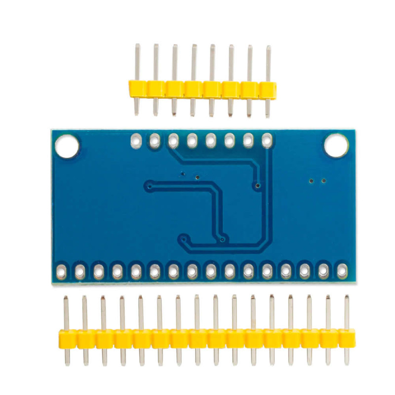
- Connection: 2.54mm pitch 16-pin and 8-pin hole rows; male headers are in the package, not soldered
- Compatible boards: Arduino, ESP32, ESP8266, STM32, Raspberry Pi Pico and any control board with digital outputs
- Operating temperature: -55°C - 125°C (chip value)
- Mounting: 2 holes on the board
- Color: Blue
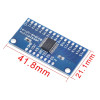
- Dimensions: about 40mm x 18mm
- Weight: about 3gr
Usage information:
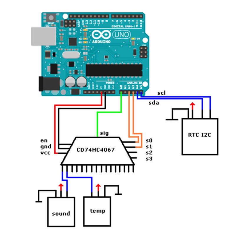
- Connect the VCC pin to the logic supply of your control board (3.3V or 5V), the GND pin to GND and the EN pin to GND. Connect the S0 - S3 pins to 4 digital outputs, and the Z pin to an analog input to read sensors or to an output to send a signal.
- To select a channel, apply the channel number in binary to the S0 (lowest bit) - S3 (highest bit) pins; for example for Y5, S0 = 1, S1 = 0, S2 = 1, S3 = 0. After the channel changes, wait a short time before reading.
- In serial communication one board connects the TX line of 16 devices to a single RX pin by selection; for bidirectional communication a second board routes to the RX lines.
Applications:
- Sensor reading; 16 analog sensors with a single analog input
- Potentiometer and slider (fader) panels
- Button and keypad reading
- MIDI controllers and audio control panels
- Soil moisture measurement; multi-point measurement in greenhouses and gardens
- Multi-point light measurement with LDRs
- Multi-point temperature measurement with NTCs
- Reading infrared sensor arrays in line follower robots
- Selecting a serial (TX / RX) line between 16 devices
- Channel scanning in test and measurement setups
Things to consider:
- The signal passing through the channels must not go below GND or above VCC. Power the board from the logic voltage of the control board: on a 3.3V board (ESP32, Raspberry Pi Pico) VCC must be 3.3V. With VCC at 5V, 5V can reach the 3.3V input through the Z pin and a 3.3V HIGH level on S0 - S3 may not be enough (the chip needs at least 3.15V for HIGH at a 4.5V supply).
- Only one channel is connected at a time. The board does not give 16 independent outputs; unselected channels stay open, and the level of channels used as digital outputs is not held.
- Each channel passes at most 25mA and has about 70Ω on resistance. Do not drive loads such as relays, motors or LED strips through this board.
- On resistance and channel switching affect analog readings; with high resistance sensors wait after selecting the channel before reading, or discard the first reading.
- On boards without analog inputs, such as the Raspberry Pi, an additional ADC is needed to read analog sensors.
Package contents:
- 1 pcs CD74HC4067 Module
- 1 pcs 16-pin male header
- 1 pcs 8-pin male header
- Note: The headers are not soldered to the board.