- Stok Durumu: Stok Var
- Marka: OEM
- SKU: RBZ.100.428
74HC4051 8 Channel Analog / Digital Switch Module
Multiplexing and Selecting Multiplexer Demultiplexer
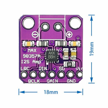
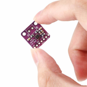
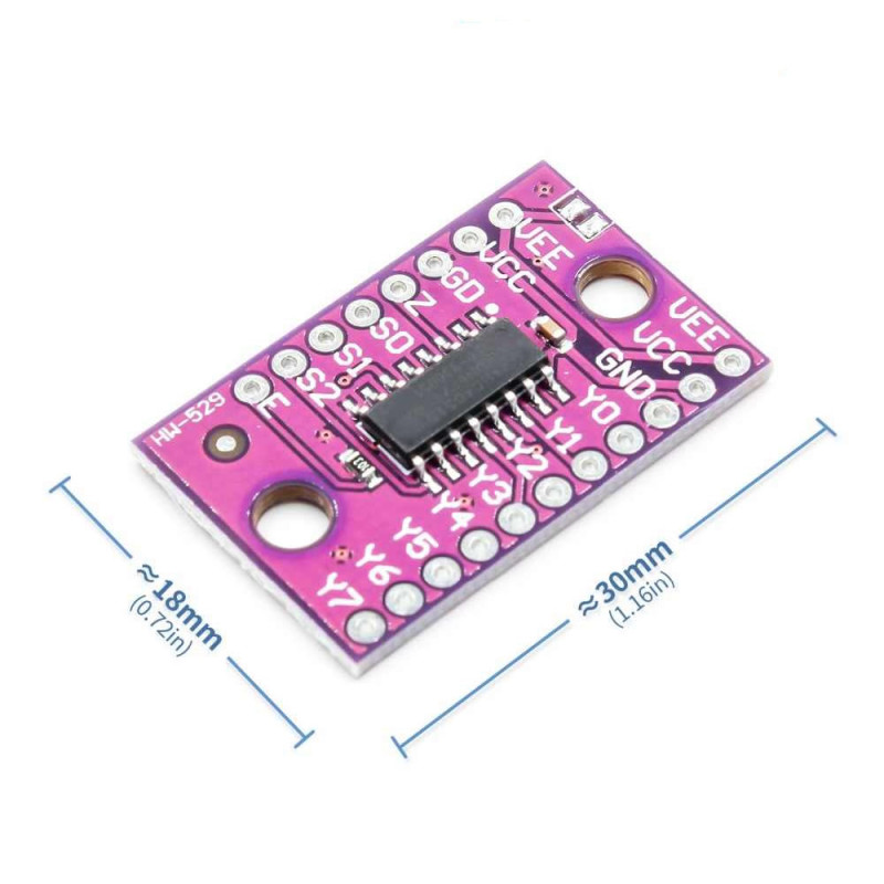
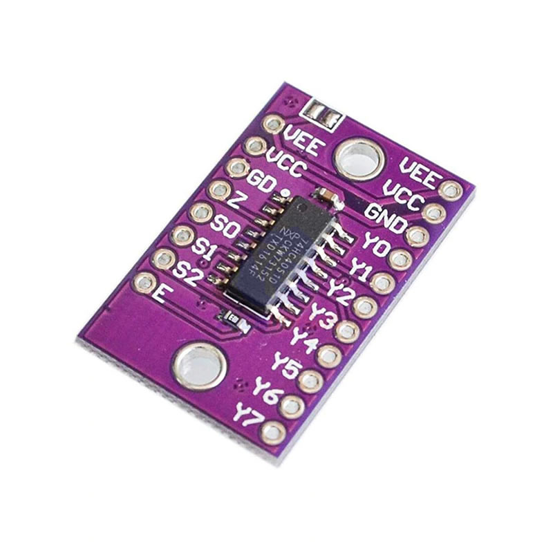
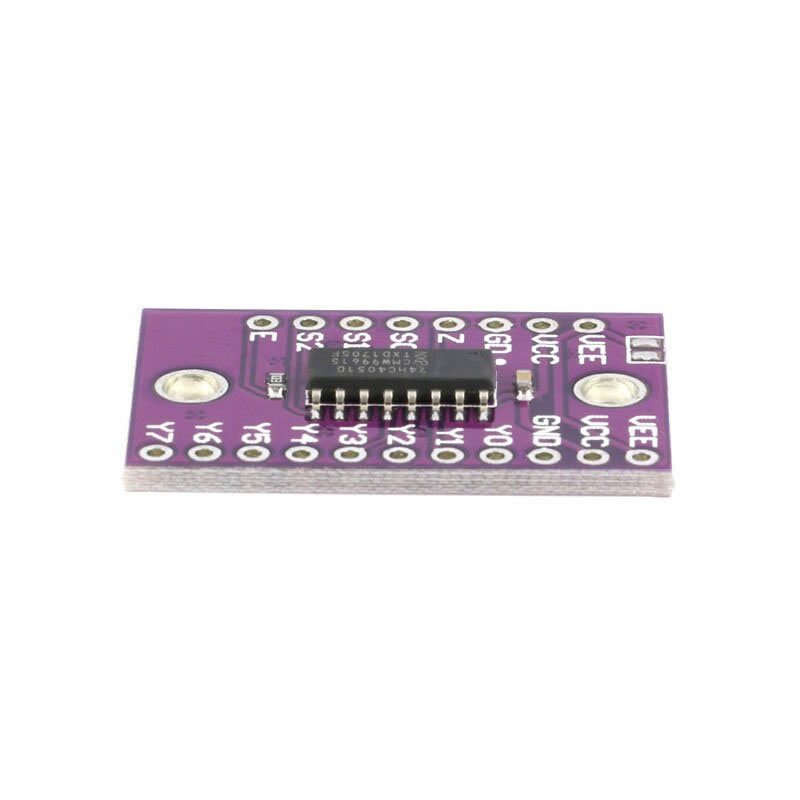
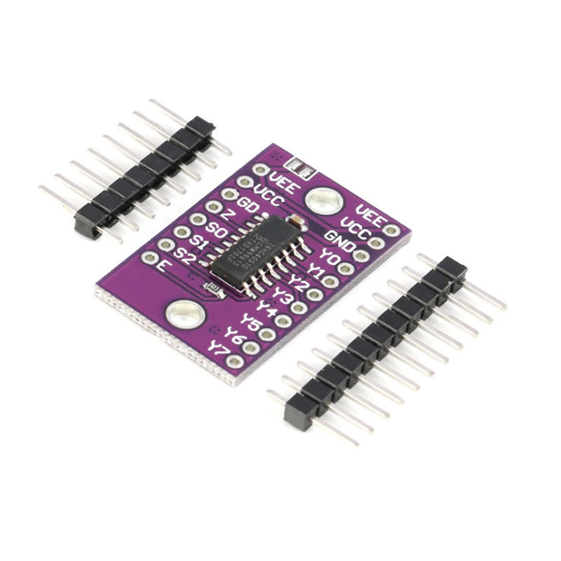
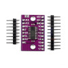
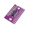
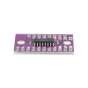
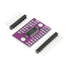
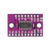
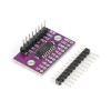
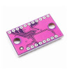
This module is an 8 channel analog / digital multiplexer board of approx. 18mm x 30mm that makes the 74HC4051 IC ready to use with 2.54mm pitch pin outputs (board code HW-529). The IC contains 8 bidirectional switches. One of the 8 channels (Y0 - Y7) is selected with the S0, S1 and S2 address pins and connected to the common Z pin. In this way 8 separate signals can be read in turn with a single analog input or digital pin, or a single signal can be distributed to 8 separate outputs.
Since the switches are bidirectional, the module works both as a multiplexer and as a demultiplexer. When used as a multiplexer (selector), the signals connected to the 8 input pins are read in turn from the common Z pin; for example 8 separate sensors can be read from a single analog input. When used as a demultiplexer, the signal on the Z pin is transferred to the selected channel; for example one TX pin can be connected in turn to the RX pins of 8 separate ICs to communicate with these devices.
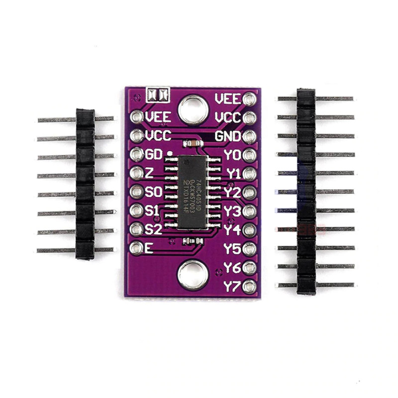
One edge of the board has the control pins (E, S0, S1, S2), the common Z pin and the supply (GND, VCC, VEE); the opposite edge has the 8 channel pins (Y0 - Y7) and a second supply group (GND, VCC, VEE). When the E (enable) pin is set to logic 1, all channels are switched off. Thanks to the VEE pin, negative analog signals can also be switched by applying a negative supply. It can be screwed inside a box with its two mounting holes. For jobs that need 16 channels, the CD74HC4067 16 channel multiplexer module is sold separately.
Key features:
8 channels with 3 pins: One of 8 channels is selected with the S0, S1, S2 address pins; only 3 digital pins and 1 analog or digital pin of the controller board are used.
Bidirectional switch: The same board is used to collect signals (multiplexer) and to distribute signals (demultiplexer); it passes analog and digital signals.
Enable pin: When the E pin is logic 1, all 8 channels are off; several modules can be connected to the same Z line and enabled in turn.
Negative signals with VEE: Negative analog signals can be switched by applying a negative supply to the VEE pin; VCC to VEE must be max. 10V. In single supply use VEE is connected to GND.
Small board, pins on both sides: On the approx. 18mm x 30mm board the control pins are on one edge and the channel pins on the opposite edge; easy to use on a breadboard and with screw mounting.
Features:
- Product type: 8 channel analog / digital multiplexer - demultiplexer module
- IC: 74HC4051 (SMD, 16 pin)
- Number of channels: 8 (Y0 - Y7) and 1 common pin (Z)
- Address select pins: S0, S1, S2 (3 pins)
- Enable pin: E, active at logic 0; all channels off at logic 1
- Operating voltage (VCC): 2V-6V (used with 3.3V and 5V controller boards)
- Negative supply (VEE): VCC - VEE max. 10V
- Signal range: Analog and digital signals between VEE and VCC
- On channel resistance: approx. 70Ω - 80Ω (at 4.5V supply)
- Channel current: max. 25mA
- Switch structure: Bidirectional; used as multiplexer and demultiplexer
- Pin pitch: 2.54mm (plugs into a breadboard after soldering a pin header)
- Pinout: E, S2, S1, S0, Z, GND, VCC, VEE / Y7 - Y0, GND, VCC, VEE
- Board code: HW-529
- Operating temperature (IC): -40°C - +125°C
- Mounting holes: 2 pieces
- Color: Purple board
- Dimensions: approx. 18mm x 30mm
Usage information:
- Connect VCC to the 3.3V or 5V output of your controller board and GND to GND. If you do not use negative signals, connect the VEE pin to GND; connect the E pin to GND or give logic 0 from a digital pin.
- Connect S0, S1, S2 to 3 digital outputs and the Z pin to an analog input (sensor reading) or a digital pin. When the binary value S2-S1-S0 is 000, Y0 is selected; when it is 111, Y7 is selected.
- After changing the channel, read after a short delay; allow time for the signal to settle. Read the sensors in turn, changing the address each time.
Areas of use:
- Reading many analog sensors from one input (LDR, NTC, gas sensor)
- Reading potentiometers and slide pots, MIDI controller
- Reading buttons and switches
- Greenhouse and pot soil moisture sensor groups
- Aquarium and water tank measuring points
- Communicating with several devices from one serial port (TX / RX selection)
- Signal distribution and led selection
- Audio and measurement signal input selector
- Line follower robot sensor array reading
Precautions:
- The switched signal must stay between VEE and VCC. While VEE is connected to GND, do not apply negative voltage or voltage higher than VCC; the IC will be damaged.
- The channels are not power switches; max. 25mA passes per channel. Motors, relays or high current leds cannot be driven directly.
- An on channel has approx. 70Ω - 80Ω resistance; it adds error to the measurement at high current or with low impedance sensors.
- Only one channel is on at a time; the 8 signals are read in turn, not at the same time.
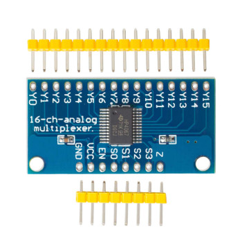
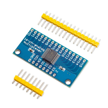
- This board has 8 channels and uses 3 address pins; its pinout differs from the 16 channel CD74HC4067 module.
Package contents:
- 1 Piece 74HC4051 Module