- Stok Durumu: Stok Var
- Marka: OEM
- SKU: RBZ.101.585
Esp32 Expansion Board Terminal Block Socket Board
Esp32-s3 44 pin Fast Prototyping Easy Connection 25.5mm 23mm Pin Pitch Kit Compatible
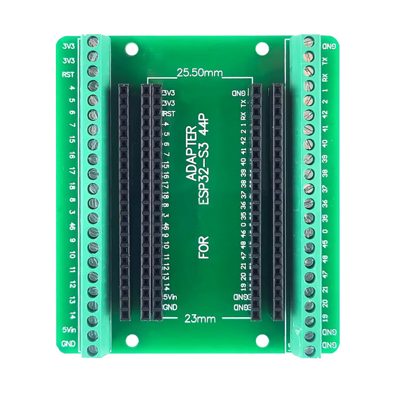
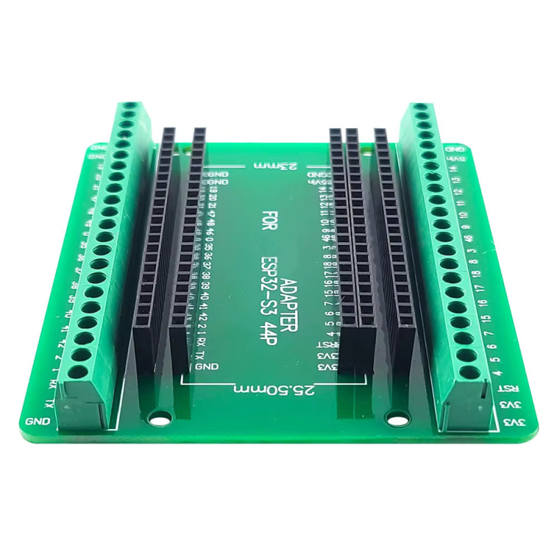
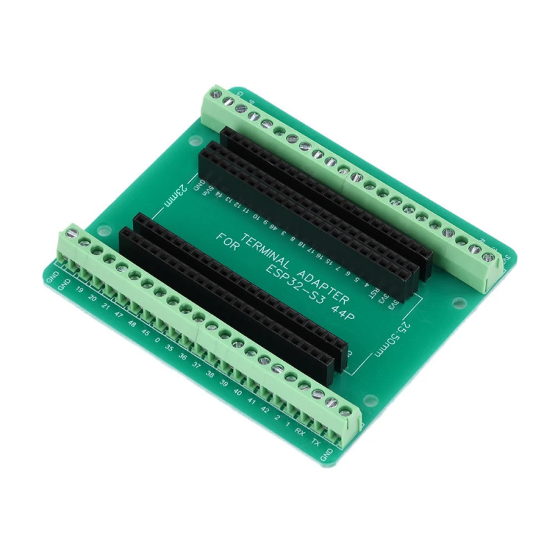
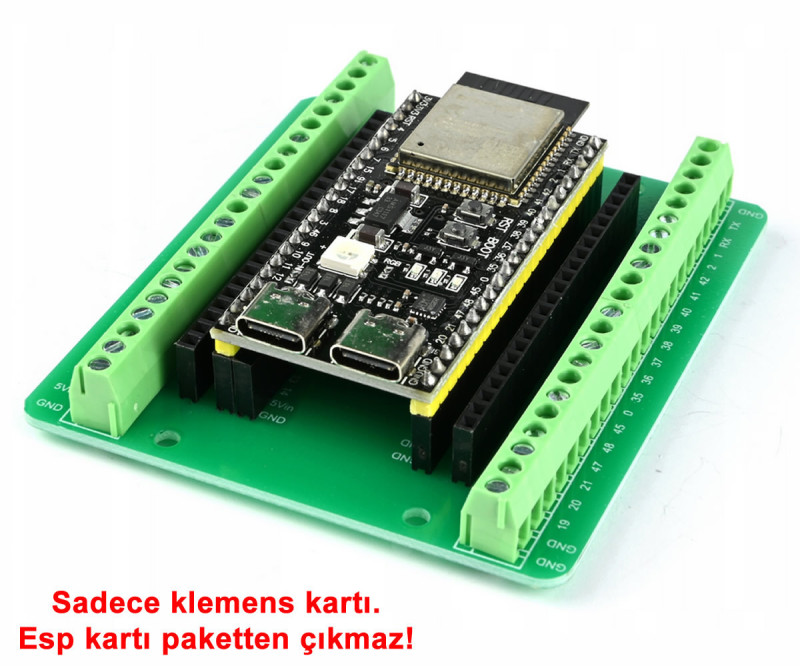
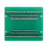
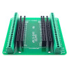
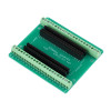
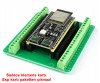
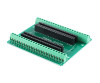
The Esp32 expansion board is a connection board that brings all pins of 44-pin ESP32-S3 development boards out to screw terminals. As the "ADAPTER FOR ESP32-S3 44P" print on the board shows, it is made for the ESP32-S3-DevKitC-1 pinout. There are separate sockets for two board widths with 25.5mm and 23mm between the pin rows; the development board plugs into the female header sockets and the wires are connected to the terminals without soldering.
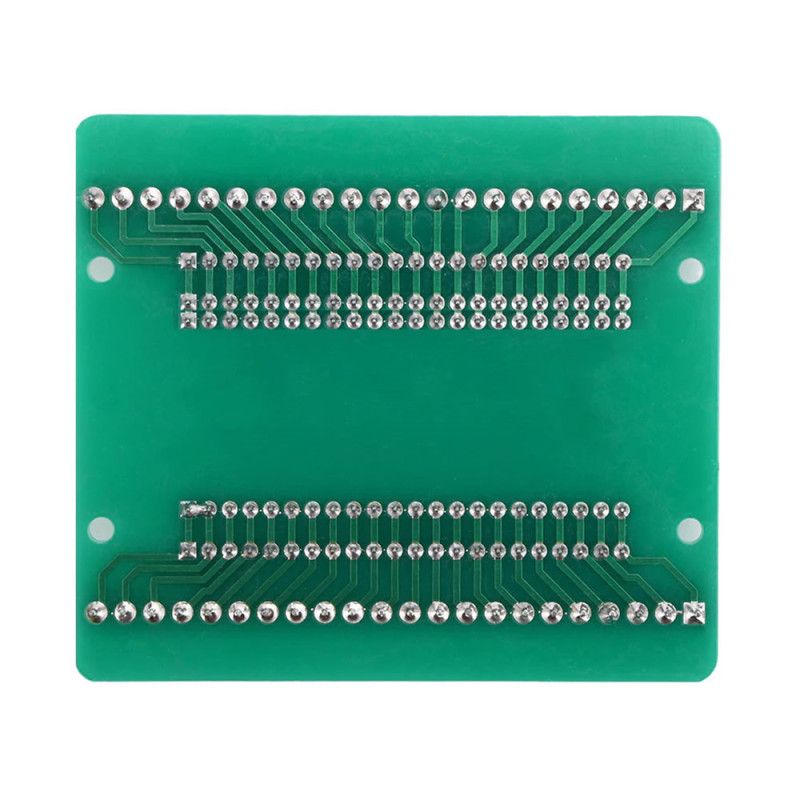
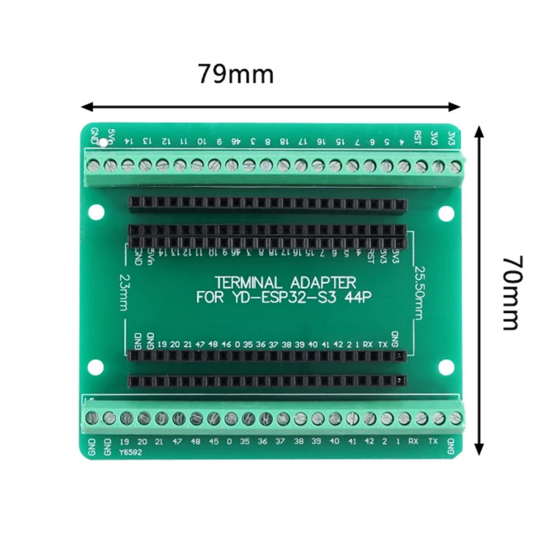
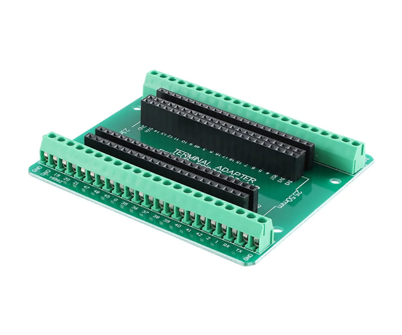
The board has 5 soldered 22-pin female headers: on the left, two socket rows for 25.5mm and 23mm boards, on the right, a common socket row, and on each side one extra row for plugging jumper wires. The 2 rows of 22 terminals along the two long edges of the board give 44 connection points in total; the pin name (3V3, RST, GPIO number, TX, RX, 5Vin, GND) is printed next to each terminal.
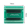
The 79mm x 70mm board is screwed into a box or panel through the 4 holes at its corners. There is no regulator or other electronic part on the board; each terminal is connected directly to the related pin of the development board. It suits applications such as home automation, greenhouse and irrigation control, where wires are connected and removed or a permanent installation is made.
Key features:
All 44 pins on terminals: The 44 pins of the ESP32-S3 board are brought out to 2 rows of 22 screw terminals; sensor, relay and power wires are connected and removed without soldering.
Two separate board sockets: There are two separate socket rows on the left side; both wide boards with 25.5mm between the pin rows and narrow boards with 23mm fit on the same board.
Extra header for each pin: Next to the terminals there is one extra female header row on each side; while a permanent connection is made to a pin with the terminal, a test or trial connection can also be made with a jumper wire.
Labeled pins: The pin name is printed next to each terminal and board socket row; there is no need to look at the pinout of the development board while wiring.
Firm fixing: With the 4 holes at the corners the board is screwed to a panel or box base.
Features:
- Product type: terminal block expansion (connection) board for 44-pin ESP32-S3 development boards
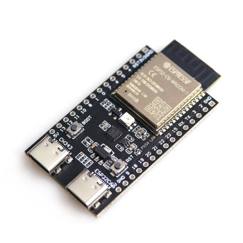
- Compatible boards: ESP32-S3-DevKitC-1 (N8R2, N8R8, N16R8) and 44-pin ESP32-S3 boards with the same pinout
- Board socket: two separate socket rows for boards with 25.5mm and 23mm between the pin rows
- Terminals: 2 rows of 22 screw terminals, 44 connection points in total
- Terminal pitch: about 3.5mm
- Female headers: 5 pcs soldered 22-pin female headers (3 board socket rows, 2 extra connection rows)
- Header pin pitch: 2.54mm (100mil)
- Left terminal row: 3V3, 3V3, RST, 4, 5, 6, 7, 15, 16, 17, 18, 8, 3, 46, 9, 10, 11, 12, 13, 14, 5Vin, GND
- Right terminal row: GND, TX, RX, 1, 2, 42, 41, 40, 39, 38, 37, 36, 35, 0, 45, 48, 47, 21, 20, 19, GND, GND
- Power terminals: 2 x 3V3, 1 x 5Vin, 4 x GND
- Circuit: passive connection board; no regulator or other electronic part, each terminal is connected directly to the related pin of the development board
- Pin labels: printed next to each terminal and board socket row (the extra header rows are not labeled)
- Installation: no soldering needed; the development board plugs into the socket, the wires are screwed into the terminals
- Mounting: 4 fixing holes at the board corners
- Material: green PCB, green terminals, black female headers
- Dimensions: 79mm x 70mm
- Weight: 42gr
Usage information:
- Measure the distance between the pin rows of your development board and plug the board into the one of the two left socket rows that matches this measure (the 25.50mm and 23mm measures are printed on the board); the right socket row is common to both widths. Plug the board so that the pin names on it face the same way as the labels on the expansion board (3V3 at top left, GND at top right).
- Loosen the terminal screw, insert the wire into the slot and tighten the screw. For power use the 5Vin and GND terminals or the USB input of the development board; do not use both together.
- For trial connections you can plug jumper wires into the extra female header row next to the terminals; make the permanent connection with the terminal.
Applications:
- Home automation; permanent connection of relay, sensor and button wires
- Greenhouse and garden irrigation control panels
- Aquarium and terrarium control setups
- Weather station and environment monitoring setups
- Permanent ESP32-S3 installation in a panel or box
- IoT applications with many sensors and relays
- Workshop and machine monitoring, counter and status reading
- Use as a robot and vehicle control board
- Training and laboratory experiments; connections that are frequently removed and refitted
- Moving from prototype to permanent installation
Things to consider:
- The board fits only 44-pin boards with the ESP32-S3-DevKitC-1 pinout. 30 and 38 pin ESP32 DevKit boards and boards with a different pinout do not fit; check the pinout and the distance between the pin rows of your board before buying.
- There is no regulator on the board; the 5Vin terminal is connected directly to the 5V pin of the development board. Apply only regulated 5V to this terminal.
- ESP32-S3 pins are 3.3V. Do not connect 5V or higher voltage signals to the GPIO terminals; connect loads such as relays and motors through a driver board.
- Plugging the development board in the wrong direction or shifted connects the power pins to the wrong terminals; check the 3V3 and GND labels before powering up.
Package contents:
- 1 pcs Esp32 Expansion Board Terminal Block Socket
- 2 pcs 22-way screw terminal rows ( Assembled )
- 5 pcs 22-pin female headers ( Assembled )
- Note: The ESP32-S3 development board is not included in the package.