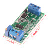
- Stok Durumu: Stok Var
- Marka: OEM
- SKU: RBZ.100.479
0-5V 0-10V to 4-20mA Voltage Current Signal Converter Module
Transmitter PLC Analog Input Valve Inverter Driver Sensor Panel Instrumentation
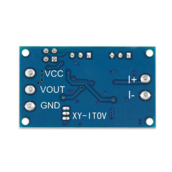
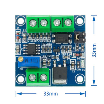
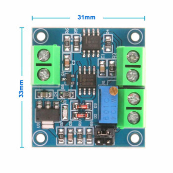
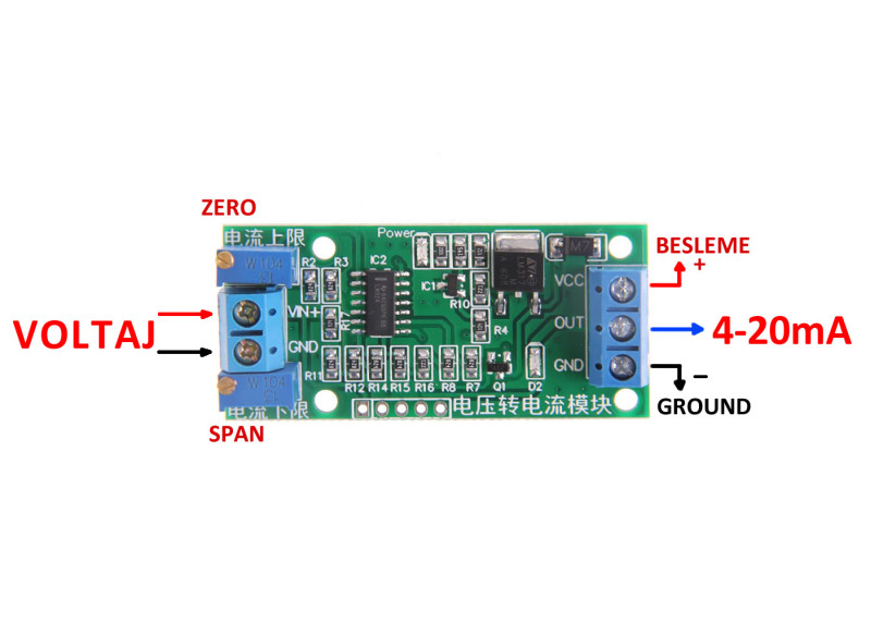
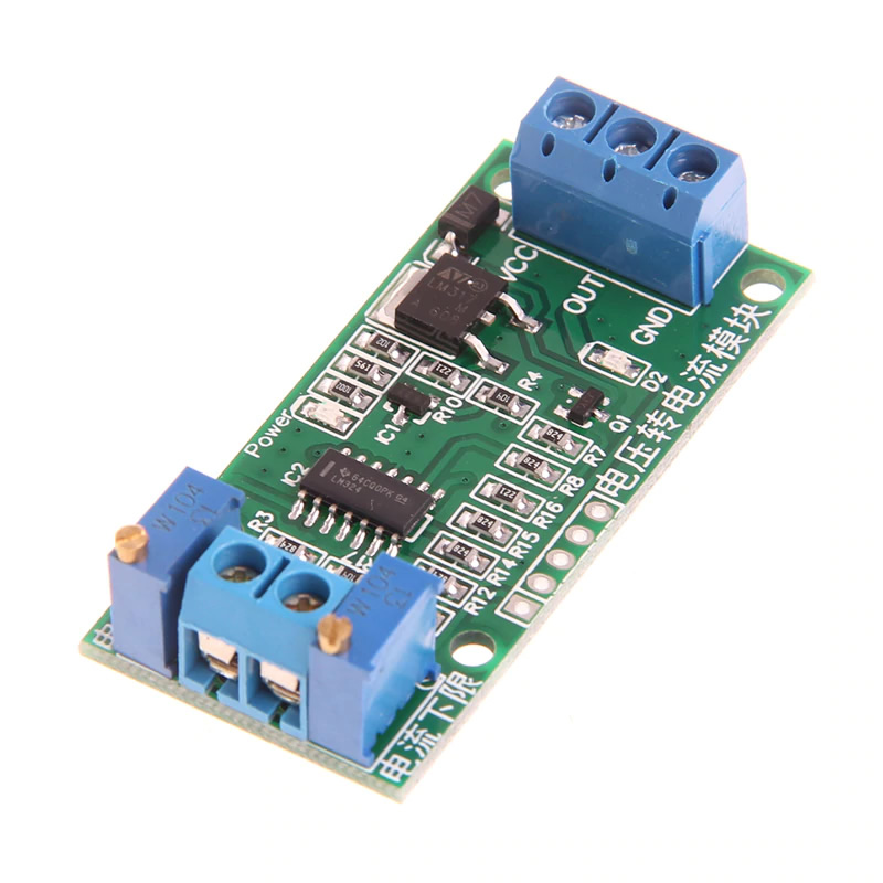
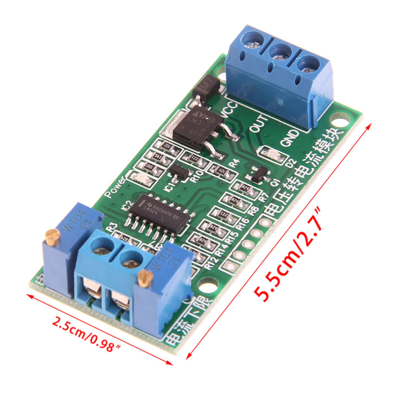
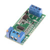
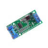
The 4-20mA voltage to current converter module converts a 0-5V or 0-10V voltage signal into a 4-20mA current signal that is linearly proportional to the input. The output is taken through a 3-wire connection made of supply positive, current output and common GND; the supply voltage must be higher than the input voltage to be converted. The board is not optically isolated, and the Power LED on it shows that supply is present.
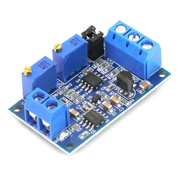
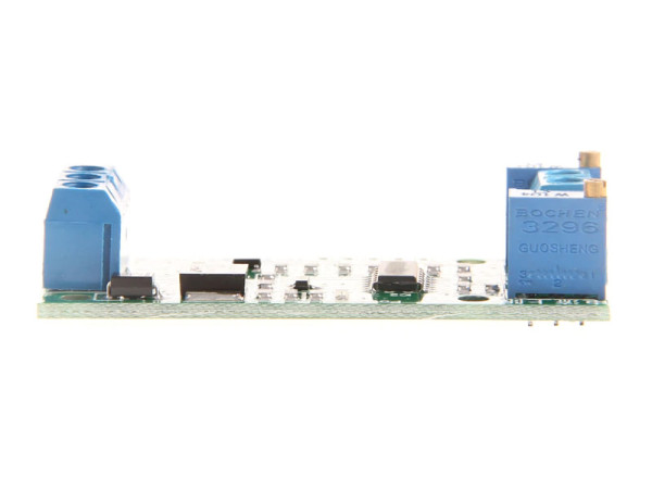
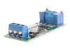
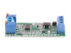
The module is powered with DC 12V - 24V. With the two precision multi-turn trimpots on the board the zero point (4mA) and the full scale point (20mA) are adjusted separately, so the output can be calibrated to the sensor or PLC input in use. The circuit is built around an LM324 operational amplifier and an LM317 regulator; supply, signal input and current output are connected with screw terminals.
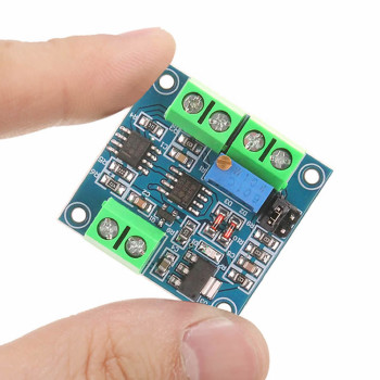
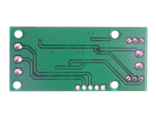
It is suitable for passing the analog output of a voltage output sensor, a potentiometer or a control board to a PLC, panel indicator, recorder, frequency inverter or proportional valve driver with a 4-20mA input. With its 55mm x 25mm size and mounting holes in the 4 corners it fits easily inside a control panel.
Features:
- Product type: Voltage to current (V/I) signal converter module
- Input voltage signal: 0-5V / 0-10V
- Output signal: 4-20mA current, linearly proportional to the input
- Supply voltage: DC 12V - 24V
- Supply condition: The supply voltage must be higher than the input voltage to be converted
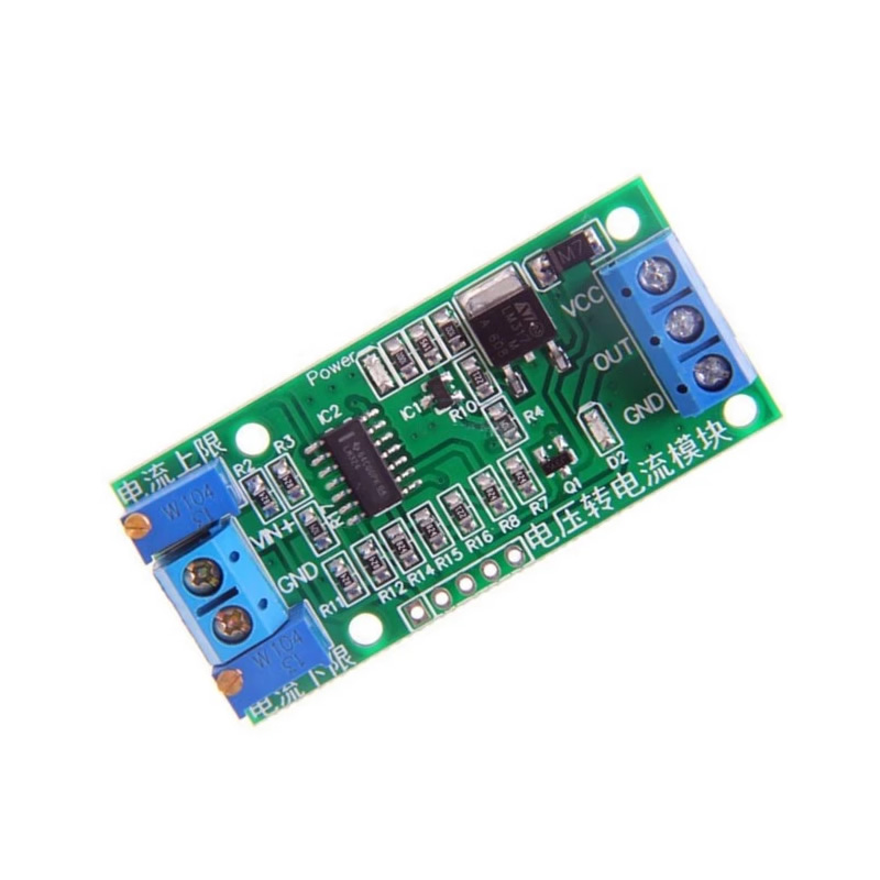
- Zero and full scale adjustment: 2 precision multi-turn trimpots (W104, 100kΩ) set the 4mA and 20mA points separately
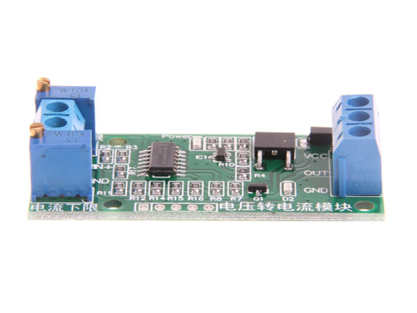
- Board marking: 电流下限 (current lower limit) and 电流上限 (current upper limit) trimpots
- Circuit: LM324 operational amplifier, LM317 regulator, transistor current output stage
- Input connection: VIN+ and GND, 2-way screw terminal
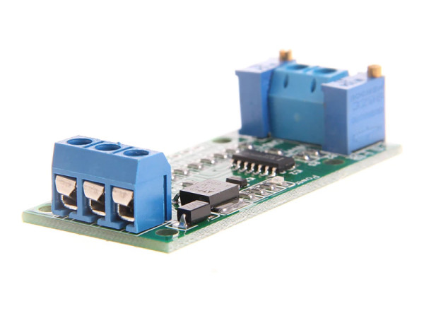
- Supply and output connection: VCC, OUT and GND, 3-way screw terminal
- Output type: 3-wire connection (supply +, current output, common GND)
- Power indicator: Power LED on the board
- Isolation: Not optically isolated
- Compatible devices: PLCs with 4-20mA analog input, panel indicators, recorders, inverters and valve drivers
- Compatible signal sources: Voltage output sensors, potentiometer, DAC output (e.g. ESP32), RC filtered PWM output (e.g. Arduino); a 3.3V output board uses only part of the 0-5V range
- Mounting: Mounting hole in each of the 4 corners
- Color: Green PCB, blue terminals
- Dimensions: 55mm x 25mm (height about 12mm)
Usage information:
- Connect the positive of the power supply to VCC and the negative to GND. Connect the voltage signal to be converted to the VIN+ and GND input; the GND of the signal source must be common with the module GND.
- The 4-20mA output is taken from the OUT terminal: connect the current input of the PLC or a measuring resistor between OUT and GND.
- Calibration: apply the lowest voltage (0V) to the input and set the output to 4mA with the 电流下限 trimpot; apply the highest voltage (5V or 10V) and set the output to 20mA with the 电流上限 trimpot. Since the two adjustments can affect each other, repeat the procedure a few times.
Application areas:
- Passing a voltage signal to a PLC analog current input
- Industrial automation and control panel applications
- Valve and actuator control (proportional valve)
- Speed reference for frequency inverters and motor drives
- Connecting Arduino and ESP32 outputs to industrial devices
- Carrying voltage output sensors over long lines
- Driving panel indicators and recorders
- Test benches, PLC trials and training setups
- Measurement laboratories and instrumentation work
Points to consider:
- The supply voltage must be higher than the input signal. Use at least 12V supply for 0-10V input; the supply must not exceed 24V.
- The module is not optically isolated. Use an additional isolator in applications that need galvanic isolation between input and output.
- The input signal must not exceed the calibrated maximum value (5V or 10V); do not connect it with reverse polarity.
- The total resistance connected to the output (PLC input + cable) is limited by the supply voltage; if 20mA cannot be reached, raise the supply to 24V or reduce the load resistance.
- Turn the multi-turn trimpots without forcing them; always make the adjustment while measuring with an ammeter in series with the output.
Package contents:
- 1 Piece 4-20mA Voltage to Current Signal Converter Module
- Note: The power adapter and connection cables are not included in the package.