- Stok Durumu: Stok Var
- Marka: OEM
- SKU: RBZ.100.802
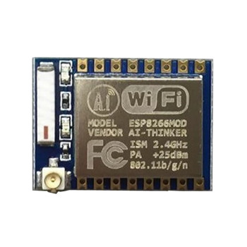
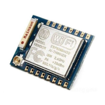
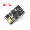
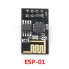
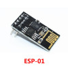
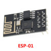
ESP-01 ESP8266 WIFI Module
IoT AT Command Smart Home Remote Control Sensor Data Logging Greenhouse Irrigation Aquarium Weather Station Socket Boiler Thermostat 2.4GHz 802.11n
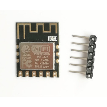
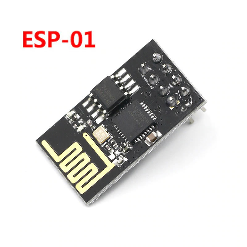
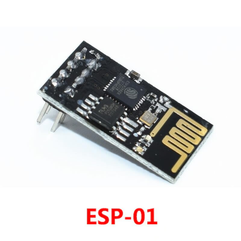
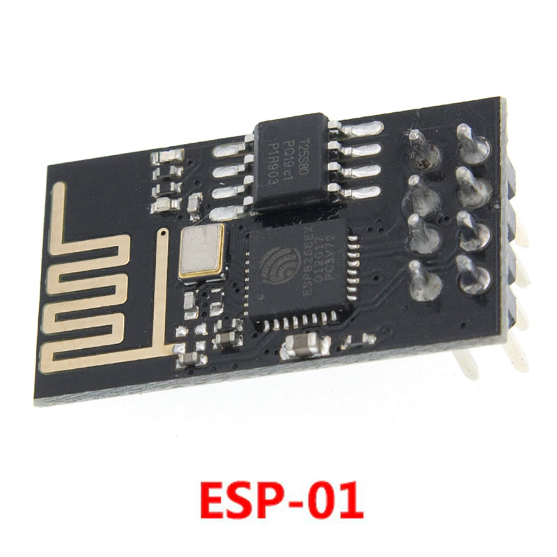
The ESP-01 is a small WiFi module built with the Espressif ESP8266EX chip and measuring 24.8mm x 14.3mm. It connects to 2.4GHz 802.11 b/g/n networks as a client (STA), as an access point (AP) or as both at the same time (STA+AP). It carries a PCB antenna, 1MB flash memory and an 8-pin (2x4, 2.54mm) male pin header; the module runs on 3.3V.
The module comes with AT command firmware installed: connected to a microcontroller over UART (TX/RX), it can join a WiFi network with simple AT commands and send and receive data over TCP/UDP. If you prefer, your own program can be loaded in place of the AT firmware; the 32-bit processor of the ESP8266 then runs the application by itself and a relay, LED or sensor can be driven from the GPIO0 and GPIO2 pins.
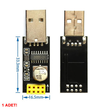
With its small size and low cost it is used to add WiFi to an existing project, send sensor data to the internet or control things remotely from a phone. A USB-TTL converter (3.3V level, FTDI type recommended) is required for programming and computer connection.
Key features:
WiFi over a serial port: Thanks to the AT command firmware it gives WiFi to any microcontroller with a UART using a few commands; the network stack runs inside the module.
Can work on its own: With the 32-bit Tensilica L106 processor of the ESP8266EX (up to 160MHz) and 1MB flash memory, a program can be loaded directly onto the module to build small WiFi devices without a separate microcontroller.
Three operating modes: It joins a network like a modem client (STA), broadcasts its own WiFi network (AP) or does both together (STA+AP); a direct connection with a phone is easy.
Very small body: The 24.8mm x 14.3mm size and on-board PCB antenna let it fit in narrow enclosures and inside sockets and switches.
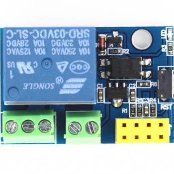
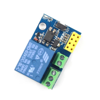
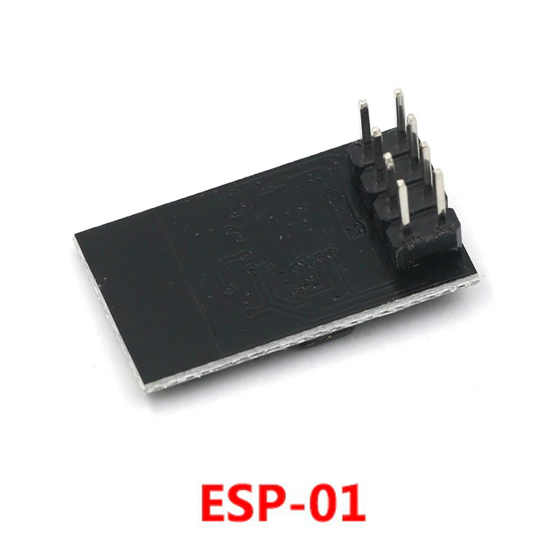
Pluggable 8-pin header: The 2x4 male pin header lets it be plugged into and removed from ESP-01 socket relay, sensor and adapter boards without soldering.
Features:
- Product type: ESP8266 based WiFi transceiver module
- Model: ESP-01
- Chip: Espressif ESP8266EX, 32-bit Tensilica L106 processor, up to 160MHz
- Flash memory: 1MB (8Mbit)
- WiFi standard: 802.11 b/g/n, 2.4GHz
- Operating modes: STA (client), AP (access point), STA+AP
- Security: WEP, WPA-PSK, WPA2-PSK
- Output power: about +20dBm (802.11b; 802.11g +17dBm, 802.11n +14dBm, chip datasheet)
- Firmware: comes with AT command firmware installed; serial speed usually 115200 baud
- Interface: UART (TX, RX) and 2 GPIOs (GPIO0, GPIO2)
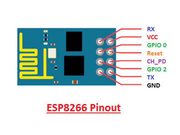
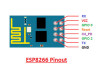
- Pinout: VCC, GND, CH_PD (EN), RST, GPIO0, GPIO2, TX, RX
- Supply voltage: 3.3V (3.0V - 3.6V)
- Pin voltage: 3.6V maximum; the pins are not 5V tolerant
- Current: average about 70mA - 80mA, peak about 300mA during WiFi transmission
- Programming: Arduino IDE (ESP8266 core), NodeMCU (Lua), MicroPython; enters upload mode when powered up with GPIO0 tied to GND
- Antenna: On-board PCB antenna
- Connection: 8-pin (2x4) male pin header, 2.54mm pitch
- Colour: Black PCB
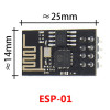
- Dimensions: 24.8mm x 14.3mm, height including pin header about 11mm
- Weight: about 2gr
Usage information:
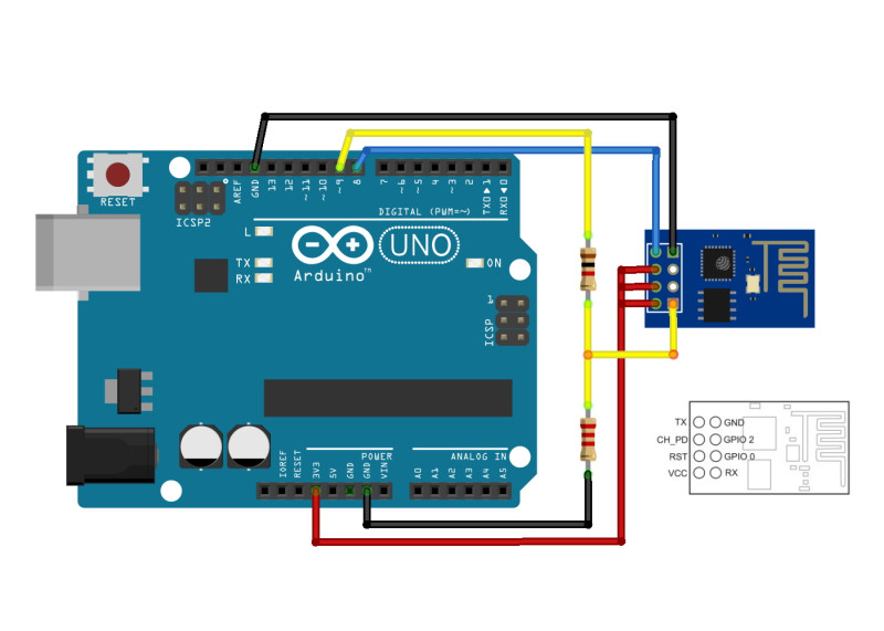
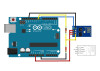
- Connect the VCC and CH_PD (EN) pins to 3.3V and the GND pin to GND. Because the module draws up to 300mA during WiFi transmission, use a separate 3.3V supply that can deliver at least 300mA - 500mA; an additional power supply may be needed.
- This is a 3.3V module; make sure it is connected only to the 3.3V lines of your microcontroller, a direct 5V connection damages the module. Besides the 3.3V supply, 5V TTL data lines must also be shifted to 3.3V: when using it with a 5V microcontroller, use a level shifter on the RX (URXD) pin of the module; a simple resistor divider or resistor-zener level shifter is enough.
- To use it with AT commands, connect the module's TX pin to the microcontroller's RX and its RX pin to TX, and select a serial speed of 115200 baud; the "AT" command should be answered with "OK".
- To load a new program, tie GPIO0 to GND and power the module (or briefly pull RST to GND), then upload with a USB-TTL converter; for normal operation release GPIO0 and restart the module.
Areas of use:
- Adding WiFi and internet connection to microcontroller projects
- Smart home and IoT (internet of things) devices
- Socket, lamp and relay applications controlled remotely from a phone
- Sending temperature, humidity and sensor data to the internet
- Weather station and environment monitoring
- Greenhouse and garden irrigation automation
- Aquarium heater, light and pump control
- Boiler and thermostat remote control
- Wireless data logging and remote monitoring
- WiFi education and experiment applications
Precautions:
- The module runs on 3.3V. Applying 5V to VCC or connecting 5V signals to the pins permanently damages the module.
- The 3.3V pins of control boards often cannot supply the 300mA peak current; if the module keeps restarting or loses its connection, use a separate 3.3V regulator.
- The module does not plug directly into a breadboard (2x4 pin layout); use jumper wires or an ESP-01 adapter board.
- When programming, make sure the USB-TTL converter works at 3.3V level; a 5V level converter can damage the module.
- GPIO0 and GPIO2 must be at certain levels at power-up (if GPIO0 is low the module starts in upload mode); circuits connected to these pins must not disturb the power-up levels.
Package contents:
- 1 Piece ESP-01 ESP8266 WiFi Module
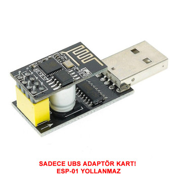
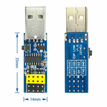
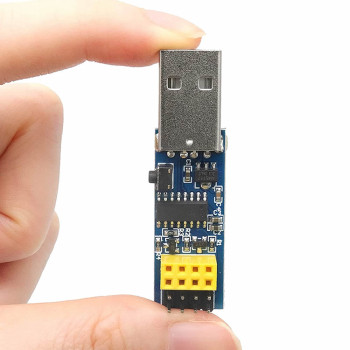
- Note: USB-TTL converter, adapter board and connection cables are not included in the package.