
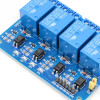
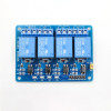
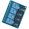
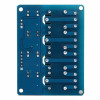
- Stok Durumu: Stok Var
- Marka: OEM
- SKU: RBZ.100.910
4 Channel 5V Relay Module
Isolated Input JD-VCC Separate Supply Smart Home Lamp Socket Fan Pump Solenoid Valve Irrigation Greenhouse Aquarium Curtain Garage Door Alarm Contactor
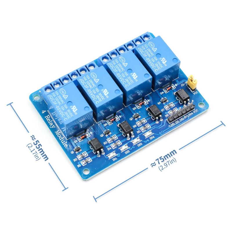
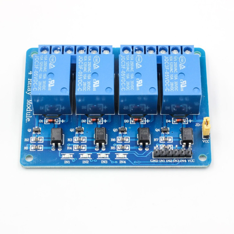
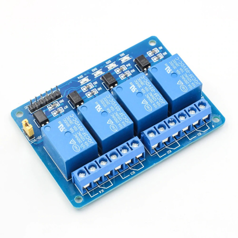
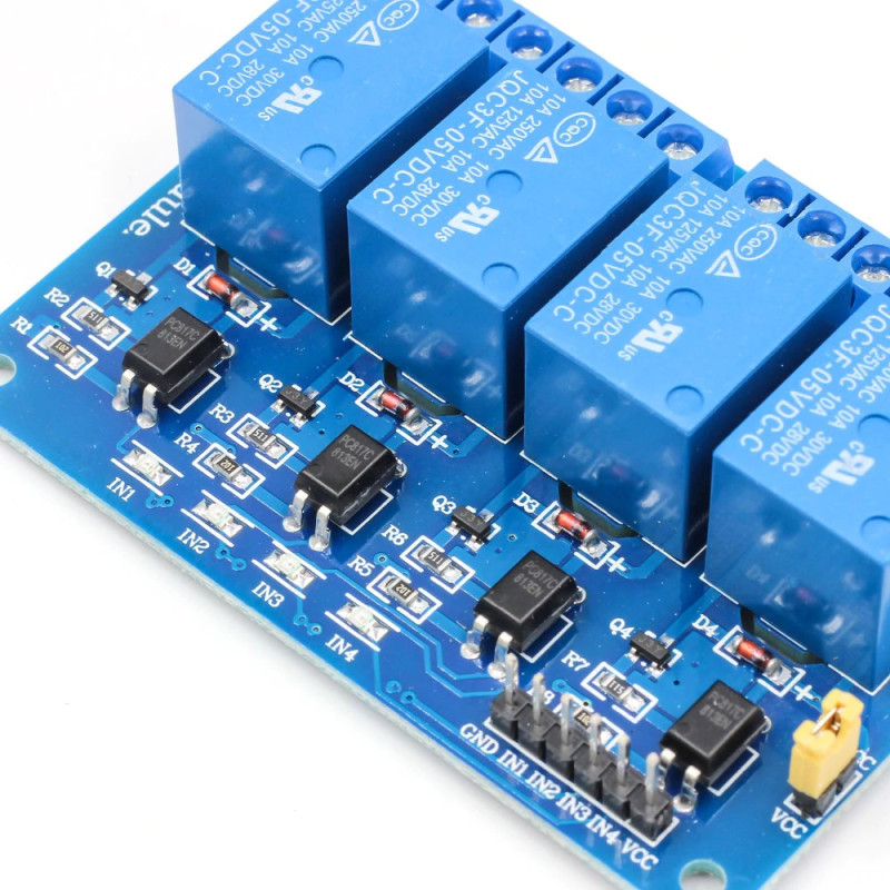
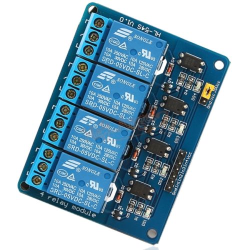
The 4 channel 5V relay module is a ready-made relay board for switching four separate loads on and off independently from a single board. The board carries 4 JQC3F-05VDC-C relays and, for each channel, a PC817C optocoupler, a driver transistor, a coil protection diode and a channel status LED. Each relay contact is rated 10A 250VAC and 10A 30VDC; the relay coil current is supplied by the driver circuit on the board, not by the control pins.
The control inputs (IN1 - IN4) are triggered at low level (LOW): when an input is pulled to GND, the relay of that channel energizes. Because the inputs are driven through optocouplers, each channel draws less than 5mA; with VCC at 5V an input below 1.2V counts as LOW and above 2.8V as HIGH, so the board can be used directly with control boards that have 5V or 3.3V outputs. While the JD-VCC jumper on the board is fitted, the relays are powered from VCC; when the jumper is removed and the relay side is powered from a separate 5V source, the control circuit and the relay circuit are separated from each other.
The NO (normally open), COM (common) and NC (normally closed) contacts of each relay are brought out to a 3-way screw terminal; loads such as lamps, fans, pumps, solenoid valves or contactor coils are connected without soldering. The 75mm x 55mm board is screwed into a box or panel through the 4 holes at its corners. It suits setups that drive several loads, such as curtains, irrigation and greenhouses, where a single channel is not enough.
Key features:
Four independent channels: 4 relays are combined on one board; each channel is switched by its own IN pin and the state of each relay is shown by its own LED.
Optocoupler isolated inputs: The input of each channel is connected to the relay driver through a PC817C optocoupler. When the JD-VCC jumper is removed and the relays are powered from a separate 5V source, noise generated by the relay coils is kept away from the control board.
Separate relay supply (JD-VCC): With the jumper fitted, the board runs from a single 5V supply. With the jumper removed, the relay coils are powered separately from the JD-VCC pin; since about 300mA is drawn when all four relays are on, the supply of the control board is not loaded.
10A contact relays: The JQC3F-05VDC-C relays are rated 10A 250VAC, 10A 125VAC, 10A 30VDC and 10A 28VDC; household lighting and small motor appliances can be switched directly.
Screw terminals and easy fixing: 12 load contacts are brought out to screw terminals; the board is fixed in a panel or box through 4 holes of 3.1mm at its corners.
Features:
- Product type: 4 channel 5V relay module with optocoupler isolated inputs
- Relay: 4 pcs JQC3F-05VDC-C (5V coil), each with one changeover contact (NO - COM - NC)
- Contact rating (AC): 10A 250VAC, 10A 125VAC
- Contact rating (DC): 10A 30VDC, 10A 28VDC
- Supply (VCC): 5V
- Control inputs: IN1, IN2, IN3, IN4; low level (LOW) trigger. The relay energizes when the input is pulled to GND and releases when the input is high or floating.
- Logic level: with VCC at 5V, LOW below 1.2V, HIGH above 2.8V; can be driven directly by control boards with 5V and 3.3V outputs
- Input current: less than 5mA per channel
- Current consumption: about 70mA with one relay on, about 300mA with all four relays on
- Optocoupler: 4 pcs PC817C, one per channel
- JD-VCC jumper: when fitted, the relays are powered from VCC; when removed, the relay coils are powered from a separate 5V source connected to the JD-VCC pin.
- Coil protection: coil protection diode (D1 - D4) and driver transistor (Q1 - Q4) on each relay
- Status LEDs: 4 pcs; the LED of each channel lights while its IN input is LOW (relay energized)
- Compatible boards: Arduino, ESP32, ESP8266, Raspberry Pi, STM32, 8051, AVR, PIC, MSP430 and any control board with digital outputs
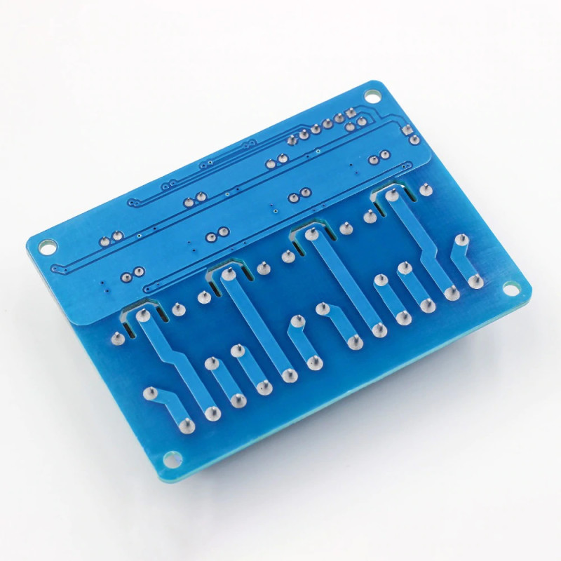
- Control connection: 6-pin male header (GND, IN1, IN2, IN3, IN4, VCC) and JD-VCC jumper header
- Load connection: 3-way screw terminal per channel (NO, COM, NC), 12 contacts in total
- Mounting: 4 pcs 3.1mm mounting holes at the board corners
- Color: Blue
- Dimensions: 75mm x 55mm x 18mm
- Weight: about 60gr
Usage information:
- Connect the VCC pin to the 5V supply, the GND pin to the GND of the control board and the IN1 - IN4 pins to the digital outputs of the control board. The inputs are low level triggered: when you set an output LOW the related relay energizes, when you set it HIGH it releases.
- For single supply use, leave the JD-VCC jumper fitted. To separate the control circuit from the relay circuit, remove the jumper, power the relay side from a separate 5V source connected to the JD-VCC and GND pins, and connect the control board only to the VCC and IN pins.
- Boards with 3.3V logic can drive the inputs directly while VCC is 5V. To separate the control board from the relay supply, remove the jumper, connect VCC to the 3.3V pin of the board and JD-VCC to a separate 5V supply.
- Connect the load that should run when the relay is energized between COM and NO, and the load that should stop when the relay is energized between COM and NC.
Applications:
- Smart home and home automation; control of lamps, sockets and lighting groups
- Curtain, roller shutter and awning motor control (two channels for open / close)
- Garage door, garden gate and door lock control
- Greenhouse and garden irrigation; zone irrigation with several solenoid valves
- Aquarium; control of light, filter, heater and air pump
- Fan, water pump and ventilation control
- Driving sirens, warning lamps and locks in alarm and security systems
- Switching large loads by driving a contactor coil
- Thermostat, timer and humidity control circuits
- IoT and remote control projects with Arduino, ESP32 and Raspberry Pi
Things to consider:
- When working with 220V mains voltage, make the connections with the power off. Use the board inside an insulating enclosure so that the terminals and solder points cannot be touched.
- The 10A ratings are the upper limit for each relay. With inductive loads with high inrush current, such as motors and compressors, work with a lower current or drive a contactor with the relay. One seller's test reported that the contacts tend to stick above about 15V with high current DC loads; keep the voltage low with high current DC loads.
- The inputs are low level triggered. If the output pin stays LOW while the control board starts or restarts, the relay may energize briefly; set the outputs HIGH at the start of the program.
- While the JD-VCC jumper is fitted, the control circuit and the relay circuit share the same supply and GND; for isolation remove the jumper and power the relay side from a separate 5V source.
- About 300mA is drawn when all four relays are on. Supply this current from the 5V supply, not from the 3.3V regulator of the control board.
Package contents:
- 1 pcs 4 Channel Relay Module 5V
- 1 pcs JD-VCC jumper ( Assembled )