- Stok Durumu: Stok Var
- Marka: OEM
- SKU: RBZ.100.693
ACS712 5A Current Sensor
Ammeter Power Meter Motor Load Monitoring Battery Charge Solar Panel Inverter UPS Overload Protection Isolated Bidirectional Terminal Block
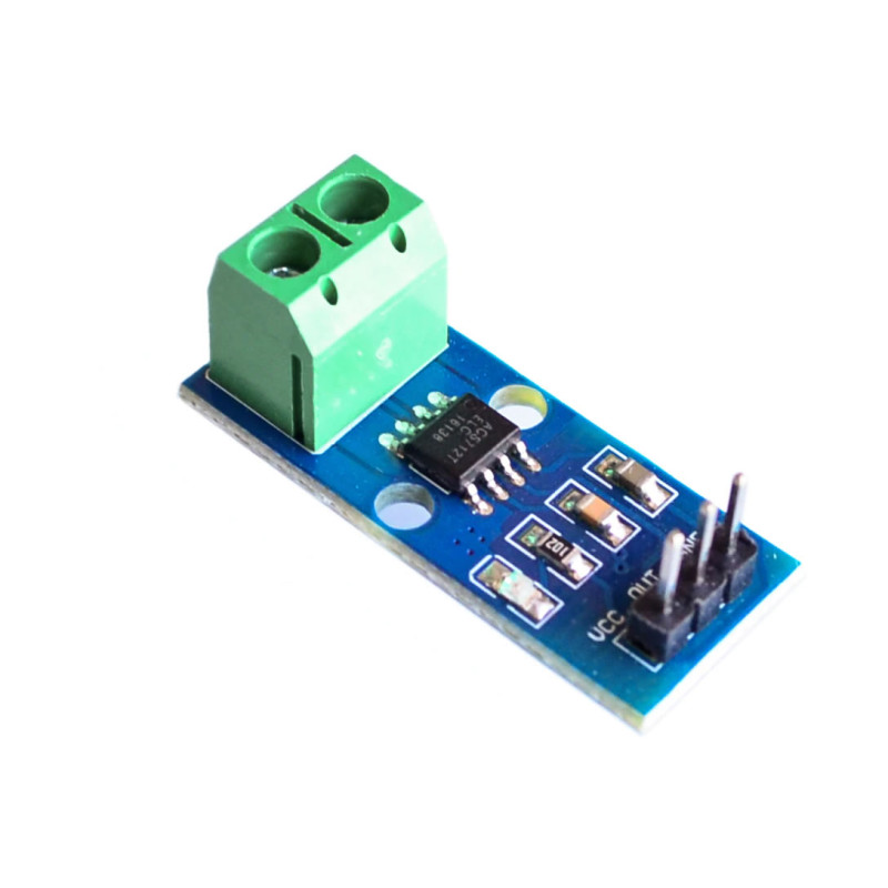
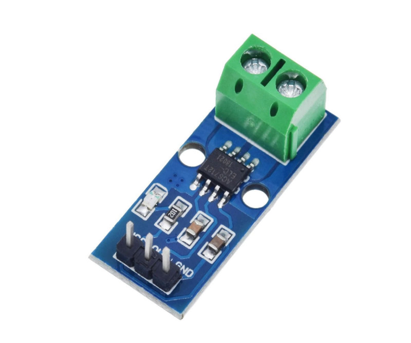
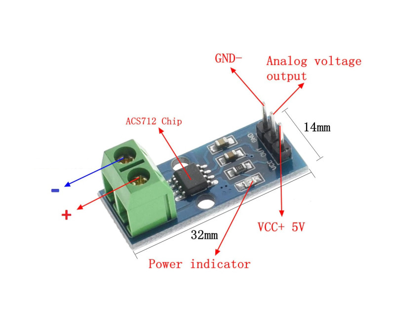
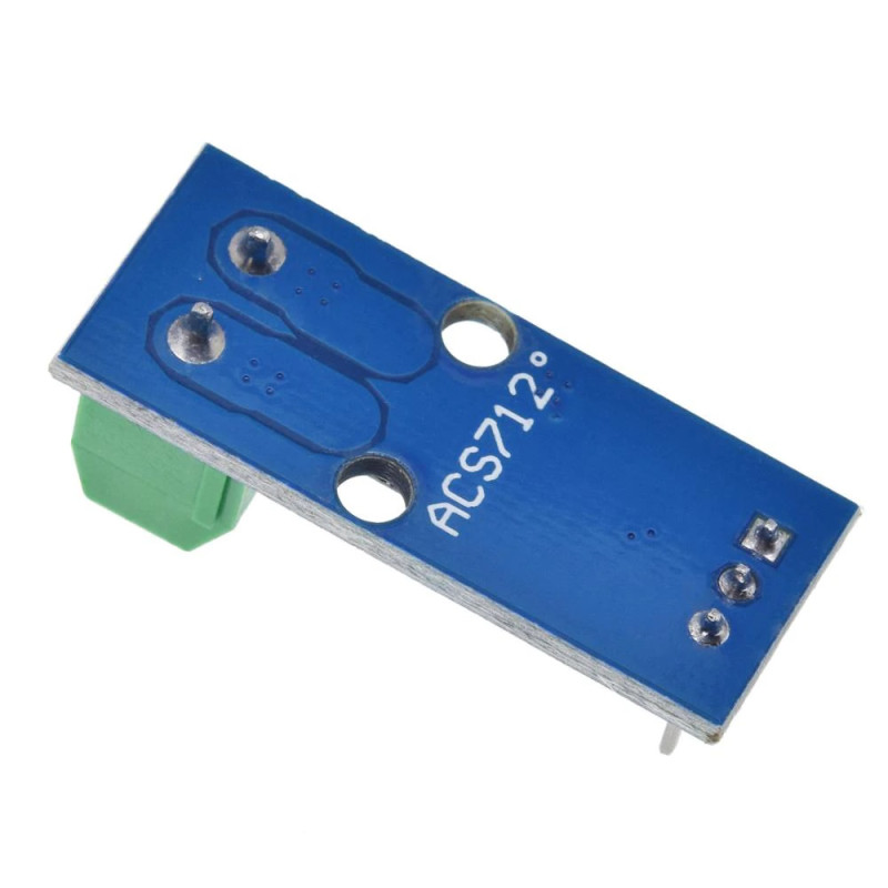
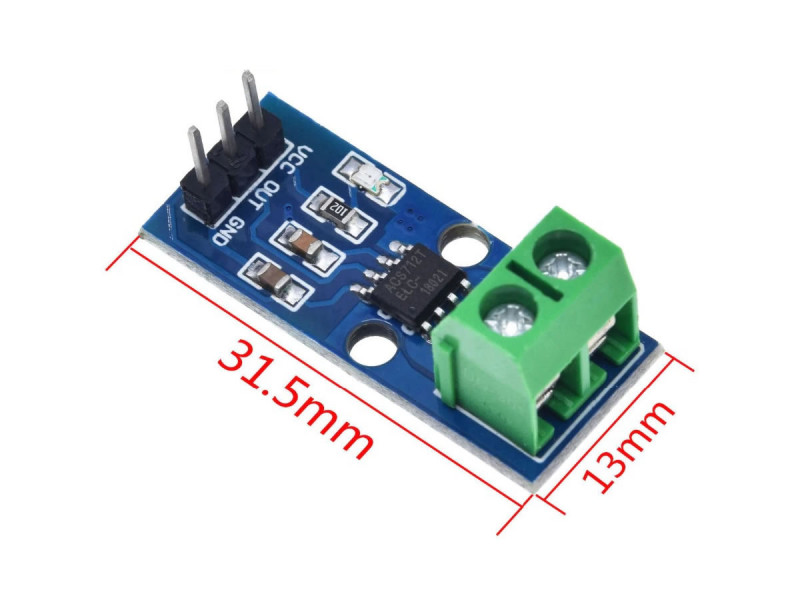
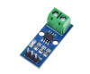
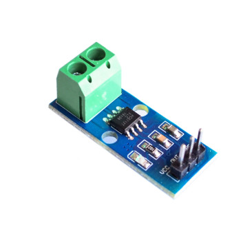
The ACS712 5A Current Sensor is a small measuring board carrying the Allegro ACS712ELCTR-05B Hall effect current sensor chip. The current to be measured passes from the 2 pin screw terminal on the board through the 1.2mΩ copper path inside the chip; the chip measures the magnetic field created by this current and gives an analog voltage proportional to the current. There is no electrical connection between the current path and the measuring side, and 2.1kVRMS isolation is provided at chip level.
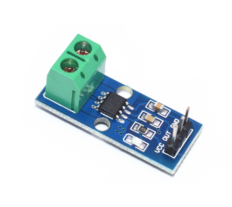
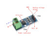
It measures AC and DC current between -5A and +5A in both directions. With 5V supply the output is about 2.5V (VCC/2) when there is no current; as the current increases in one direction the output rises 185mV per ampere, and it falls at the same rate in the opposite direction. The output is taken from the 3 pin male header labelled VCC, OUT and GND and read by the analog input (ADC) of the control board.
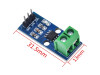
The board is about 31mm x 13mm in size and weighs about 5gr; it is fixed in an enclosure with two mounting holes. There are also 20A and 30A versions of the same board; this listing is for the most sensitive 5A version (185mV/A), which gives the highest resolution at small currents.
Key features:
AC and DC, bidirectional measurement: It measures direct and alternating current between -5A and +5A; the direction of the current is seen from the output being above or below 2.5V.
185mV/A sensitivity: The 5A version is the most sensitive member of the family; every 1A of current changes the output by 185mV, so small motor and battery currents are read clearly.
Isolated measurement: There is 2.1kVRMS isolation at chip level between the current path and the signal side; the measured circuit stays electrically separate from the control board.
Low loss, fast response: Because the current path resistance is 1.2mΩ, voltage drop and heating in the measured circuit are very low; 5µs response time and 80kHz bandwidth follow fast current changes.
Ready connection: The current path is connected with the screw terminal and the signal side with the 3 pin header; no soldering is needed.
Features:
- Product type: Hall effect AC / DC current sensor board
- Sensor chip: ACS712ELCTR-05B (SOIC-8)
- Measuring range: -5A ... +5A (AC and DC, bidirectional)
- Sensitivity: 185mV/A
- Supply voltage: 5V (4.5V - 5.5V)
- Output at zero current: VCC/2 (about 2.5V at 5V supply)
- Output type: analog voltage, proportional to the supply voltage
- Total output error: 1.5% (25°C), 4% (-40°C - 85°C)
- Response time: 5µs (chip value)
- Bandwidth: 80kHz (chip value)
- Current path resistance: 1.2mΩ
- Isolation: 2.1kVRMS (chip level)
- Current connection: 2 pin screw terminal (connected in series with the measured line)
- Signal connection: 3 pin male header (VCC, OUT, GND)
- Compatible boards: Arduino, ESP32, STM32, Raspberry Pi (with external ADC) and all control boards with analog input
- Operating temperature: -40°C - 85°C (chip)
- Mounting: 2 mounting holes
- Color: blue board, green terminal block
- Dimensions: about 31mm x 13mm
- Weight: about 5gr
Usage information:
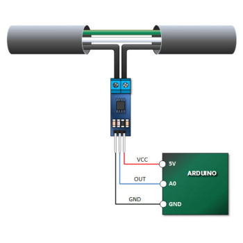
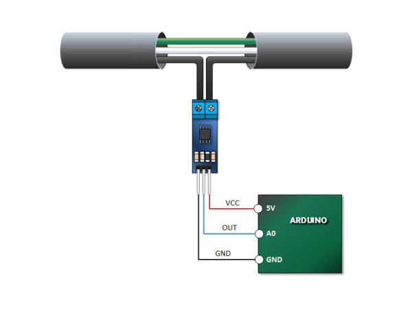
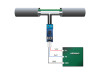
- Cut the line to be measured and connect its two ends to the screw terminal; the sensor goes in series with the load. Connect VCC to 5V, GND to the GND of the control board and OUT to an analog input.
- Current (A) = (OUT voltage - voltage at zero current) / 0.185. Measure the voltage at zero current once with the circuit unloaded and store it in software; the 2.5V value may differ by a few mV from board to board.
- With AC current the output swings around 2.5V; to find the effective (RMS) value, take many samples over one period and calculate the square root of the mean of their squares.
- With a 10 bit ADC and 5V reference one step is about 4.9mV, that is about 26mA. Average several readings to reduce noise.
Application areas:
- Building a digital ammeter and power meter (wattmeter)
- DC motor current monitoring and stall (overload) detection
- Battery charge and discharge current measurement
- Solar panel and charge controller monitoring
- Inverter and UPS load monitoring
- Overload protection and electronic fuse circuits
- Energy consumption measurement of small home appliances
- LED lighting and power supply current measurement
- 3D printer and CNC stepper motor supply current monitoring
Things to consider:
- This board is the 5A version; to measure continuous current above 5A use the 20A or 30A version. Outside the measuring range the output saturates and a wrong value is read.
- The 2.1kVRMS isolation is the chip value; on the board the distance between the current terminal and the pins is short. If it is used on a mains (220V) line, put the board in an insulated enclosure, do not touch it while in operation and make the connection with the power off.
- With 5V supply the output changes between about 1.6V and 3.4V over the ±5A range (2.5V ± 5 x 0.185V) and moves toward the supply voltage outside this range. On boards with 3.3V analog input (such as ESP32, STM32) currents above about +4.3A cannot be read; reduce the output with a voltage divider.
- A Hall effect sensor is affected by external magnetic fields; do not place the board near magnets, motors and transformers. Tighten the terminal screws well, a loose connection causes heating.
Package contents:
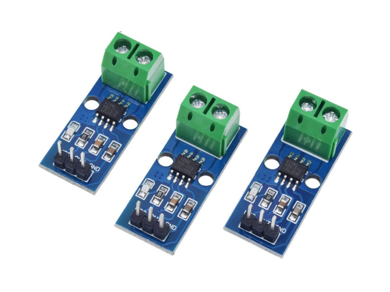
- 1 Piece ACS712 5A Current Sensor
- 1 Piece 2 pin screw terminal ( Assembled )
- 1 Piece 3 pin male header ( Assembled )
- Note: Control board and connection cables are not included in the package.