- Stok Durumu: Stok Var
- Marka: OEM
- SKU: RBZ.101.759
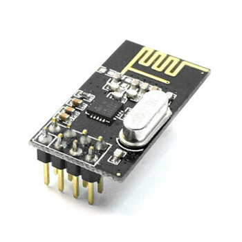
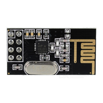
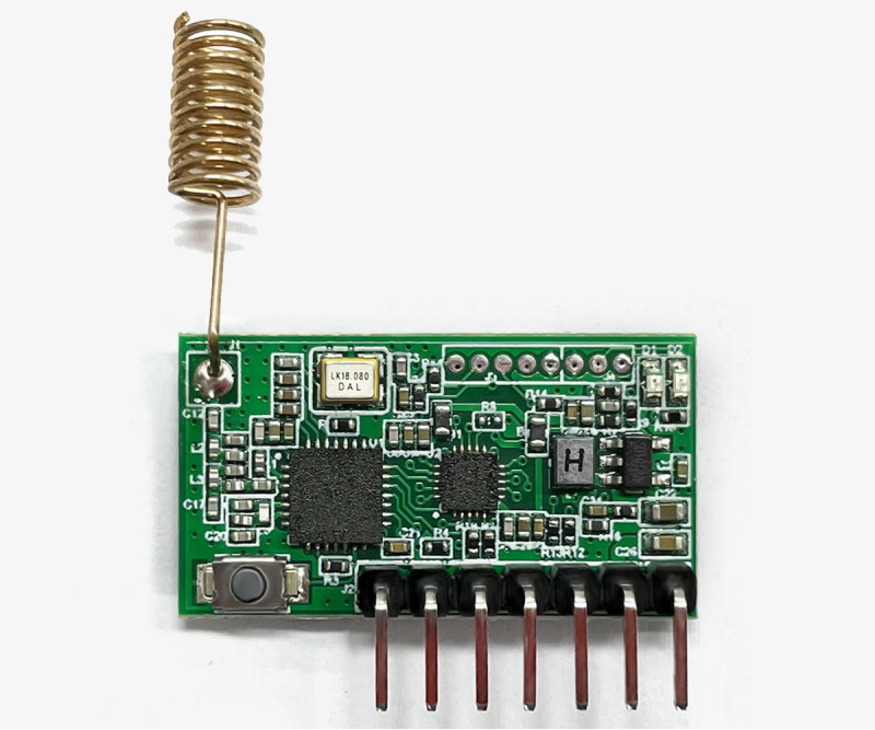
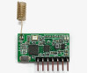
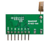
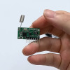
RX480E-868 Transceiver Module 4 Channel 868Mhz Receiver Transmitter QIACHIP
FSK Wireless Remote Control Learnable Receiver and Transmitter Remote Control Learning
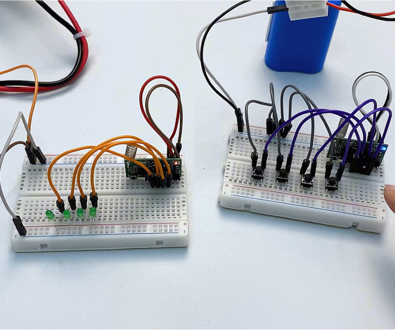
You need to buy two units and use one as the transmitter and the other in receiver mode.
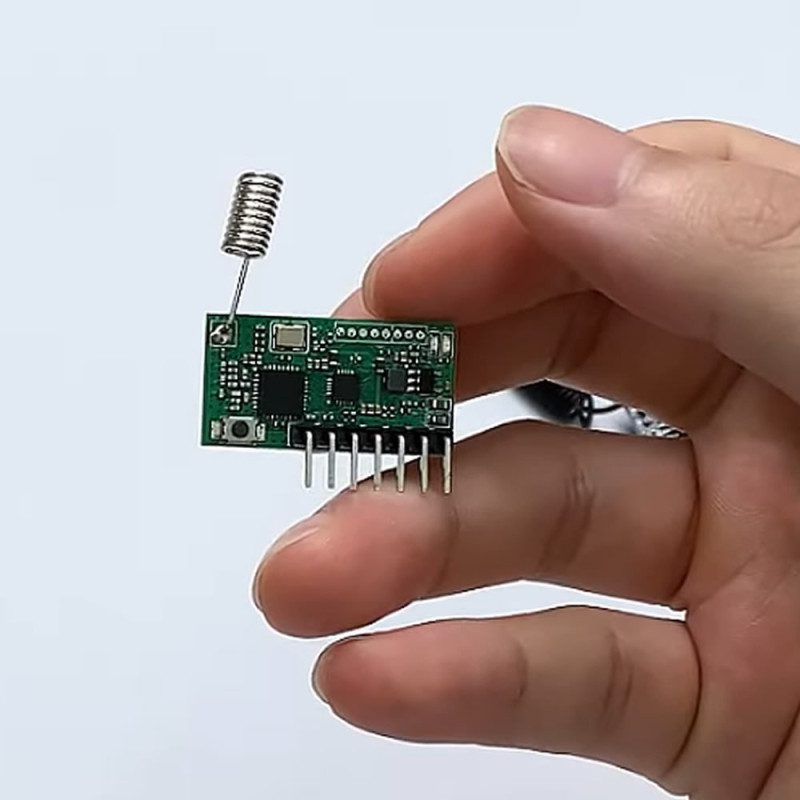
RX480E-868 is a 4 channel FSK transceiver module produced by QIACHIP and operating at 868MHz frequency. The module can be used as both receiver and transmitter; the mode can be changed with the button on it. It can operate independently without requiring an external processor. Pairing is achieved with the code learning method, and up to 32 transmitter modules can be stored in the internal memory. There are three different operating modes.
Thanks to its wide operating voltage range, it can be integrated into different systems. Depending on the supply voltage, it can communicate between 80 meters and 400 meters. It can be directly adapted to systems using the RX480E-433 module since the pin structure does not change.
Features:
- RX480E-868 Transceiver Module
- Operating voltage: Dc 5V to 24V
- Frequency: 868MHz
- Transmission distance: 300m-400m (depending on antenna type and environmental conditions), 80m to 200m below 7V
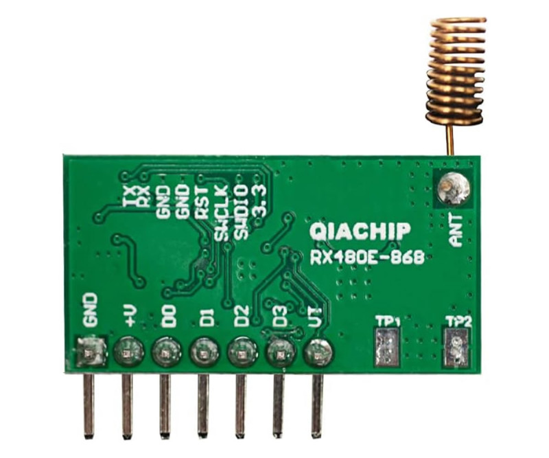
- Number of channels: 4 (D0, D1, D2, D3)
- Modulation: FSK, bidirectional data transmission
- Receiver sensitivity: -112dBm
- Receiver current consumption: 23mA
- Transmitter power: 20dBm
- Transmitter current consumption: 123mA
- Operating modes: momentary, toggle, latched/interlock
- Internal memory: up to 32 transmitter addresses can be stored
- Does not require an external mcu processor, can operate independently
- Code learning: Does not require manual coding
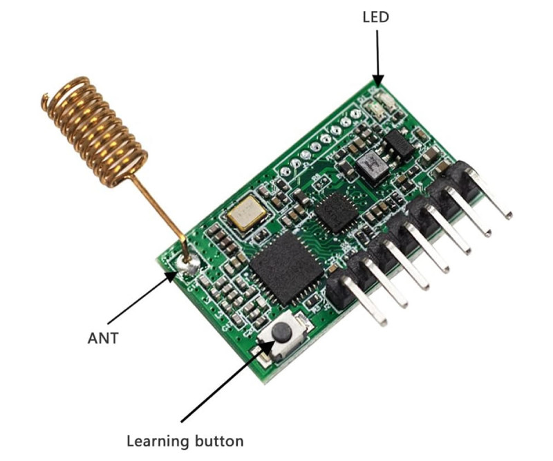
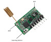
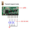
- Blue led indicator: Transmitter mode
- Red led indicator: Receiver mode
- Color: Green
- Operating temperature: -10C / 60C
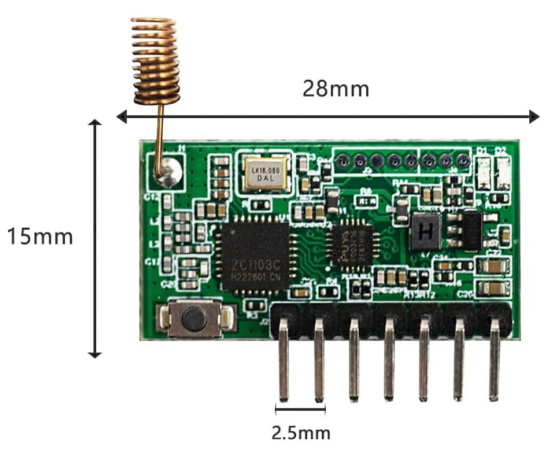
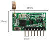
- Dimensions: 15mm x 28mm
- Weight: 2gr
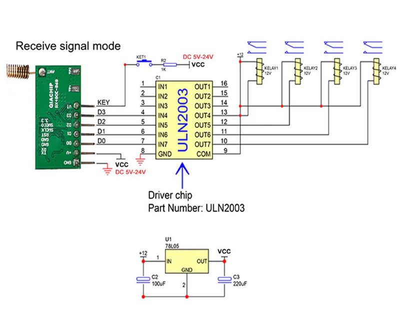
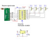
Pin definitions in receiver mode:
- GND: Power supply negative connection, DC 5V to 24V
- +V: Power supply positive connection, DC 5V to 24V
- D0: High level output pin
- D1: High level output pin
- D2: High level output pin
- D3: High level output pin
- VT: External programming button connection
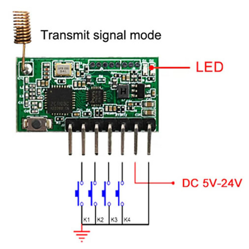
Pin definitions in transmitter mode:
- GND: Power supply negative connection, DC 5V to 24V
- +V: Power supply positive connection, DC 5V to 24V
- D0: Transmitter control pin (low level trigger input)
- D1: Transmitter control pin (low level trigger input)
- D2: Transmitter control pin (low level trigger input)
- D3: Transmitter control pin (low level trigger input)
- VT: External programming button connection
Areas of use:
- Wireless remote control switches
- Remote motor control
- Security and alarm systems
- Access control systems
- Building automation and fire protection
- Street lighting control systems
- Smart home controllers
- Smart agriculture applications
- Arduino and development board projects


Package contents:
- 1 Piece RX480E-868 Transceiver Module
Youtube product usage video: https://www.youtube.com/watch?v=NOnn7bjXKho

Usage: To correctly establish the usage logic of the module, the following order should be observed: first it is determined whether the module will be used as receiver or transmitter, then if in receiver mode the operating mode is selected, afterwards the transmitter key is registered or in transmitter mode a trigger is applied from the inputs. Although this structure seems simple at first glance, performing the mode selection, pairing and deletion operations in the correct order is important for the installation to work without problems.
Receiver transmitter setting: RX480E-868 is an RF module that can operate as both receiver and transmitter on a single board. The operating type of the module is changed via the learning button. To switch from receiver mode to transmitter mode, the learning button is pressed 5 times. The blue led flashes 2 times to indicate that transmitter mode has been entered. To put the module back into receiver mode, the learning button is pressed 5 times again; this time the red led flashes 5 times. In receiver mode it decodes the signal coming from the remote control and performs the operation on the D0, D1, D2, D3 outputs. In transmitter mode it sends the stored RF signal according to the triggers given from the input pins.
The basic logic of usage in receiver mode is to select the operating mode by pressing the learning button a certain number of times and then to press the key of the transmitter to be paired. After the mode is selected, when the transmitter key is registered, the red led on the receiver flashes 5 times to indicate that the pairing is complete. On every successful reception the blue led on the transmitter side flashes 2 times. When power is not supplied to the receiver, the blue led does not light; this feature can be used to verify the connection. Thanks to this structure, a remote control controlled system can be set up directly without using an external processor.
Momentary mode: It is selected by pressing the learning button 1 time. This mode works with momentary contact logic. As long as the key of the paired transmitter is held pressed, the relevant output is active. When the key is released, the output turns off. It is suitable for door triggering, short duration driving, doorbell, instantaneous control and pulse logic applications that must operate while the button is pressed.
Toggle mode: It is selected by pressing the learning button 2 times. This mode works with on-off memory logic. When the paired key is pressed once, the relevant output becomes active and stays in this state. When the same key is pressed again, the output turns off. It is used in applications such as remote on-off, lamp control, system enable-disable, pump or relay control.
Latched mode: It is selected by pressing the learning button 3 times. In this mode, whichever key is activated, only the output belonging to it stays active, the other outputs become passive. If two keys are pressed at the same time, all outputs return to the passive state. This mode is suitable for channel selection, direction selection, control structures where a single channel must stay active and preventing mixed commands.
The general flow during pairing is as follows: first the learning button is pressed the number of times corresponding to the desired operating mode, the module shows the selection with the led, then the relevant key of the transmitter to be registered is pressed. After successful registration the module stores this key in memory and from then on, when the same command arrives, it drives the relevant output according to the selected operating logic. For this reason, first the operating mode and then the remote control key selection must be made.
To delete the registered transmitters, the learning button is pressed 8 times. The red led flashes 8 times and goes off. After this operation all outputs return to low level and the registered transmitter addresses in memory are cleared. After clearing, the module can be paired again with new transmitters. This operation is used especially when an incorrect registration has been made, when switching to a different remote control group or when the installation will be redone from scratch.
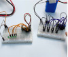
The usage logic in transmitter mode is also simple. After the module is put into transmitter mode, the previously learned RF command is sent with the low level triggers applied to the input pins. In this way, wireless command transmission can be performed by giving a trigger from another electronic board, button, sensor or microcontroller output. That is, the module is not only a receiver working with a remote control, but can also be used as a transmitter generating RF signals from another system.