- Stok Durumu: Stok Var
- Marka: Expkits
- SKU: RBZ.200.153
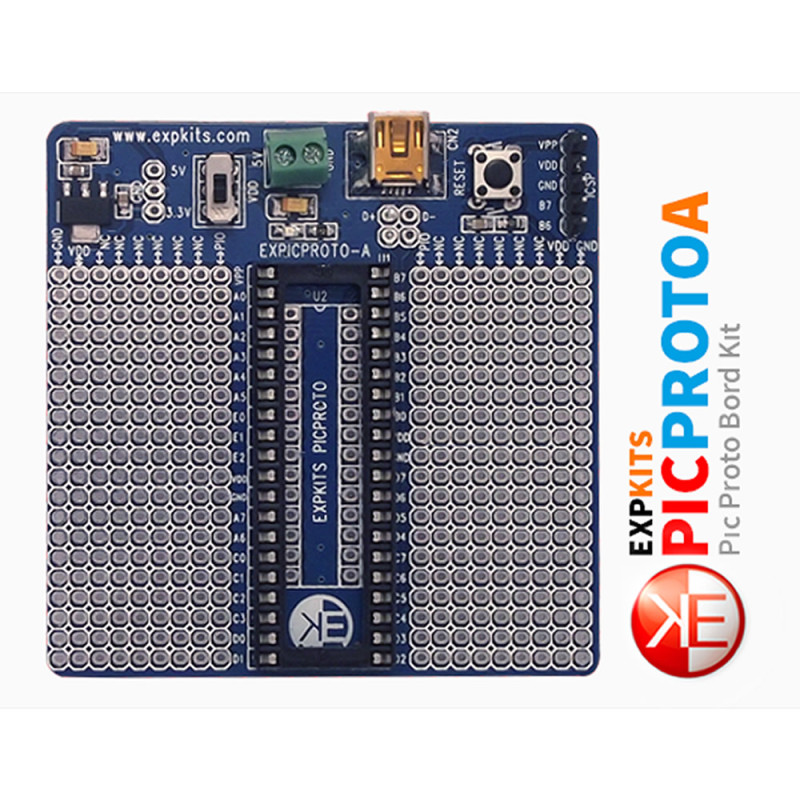
EXPICPROTOA EXPKITS Mini 8 Bit Microchip PIC Development Training Board
There is a version with 40 pin or 28 pin IC socket soldered. You must state which one you want to buy.
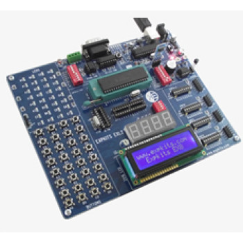
EXPICPROTOA is a small 70x70mm experiment and development board designed by Expkits for Microchip 8 bit PIC microcontrollers. A 40 pin (or 28 pin) IC socket sits in the middle of the board; the basic connections a PIC needs to run, decoupling capacitors, reset button, supply selection and ICSP programming socket are ready on the board. You can plug a PIC into the socket and start programming without building the basic circuit first.
On both sides of the socket there are 2 solderable experiment areas made of empty pads. All pins of the PIC are connected to the test points on the right and left of the socket; a pin is connected to the circuit built in the adjacent experiment area with a short wire. The outermost rows of the experiment areas carry 1 row of GND and 1 row of VDD supply line, which feed the external circuits.
The board is powered with 5V DC through the 2-way terminal block or from a computer through the mini USB socket. The 1117 LDO regulator on the board produces 3.3V; a switch selects 5V or 3.3V for the VDD line, so PICs running at 3.3V can also be used. The connections needed for USB communication are ready and separated from the circuit with 2 jumpers. The board is sold in two versions with a 40 pin or 28 pin socket soldered; please state which one you want when ordering.
Key features:
Plug-and-run PIC circuit: Decoupling capacitors, reset button and supply lines are ready on the board. An 8 bit PIC placed in the socket can be programmed through the ICSP socket without building an extra basic circuit.
Solder experiment area on both sides: There are 2 pad areas to the right and left of the socket. Every pin is connected to the test point next to it, so LEDs, buttons, sensors or an LCD are connected with short wires.
5V / 3.3V selection: The board is supplied with 5V through the terminal block or mini USB; the 1117 LDO produces 3.3V. The voltage selected with the switch goes to the VDD line and to the supply rows of the experiment areas.
USB communication connection: The D+ / D- lines of the mini USB socket can be connected to the PIC with 2 jumpers. Under the board there is an 0805 capacitor pad connected to pin C3; on USB PICs such as PIC18F2550 / PIC18F4550 this pin is VUSB, and the capacitor of the internal USB regulator is fitted here.
Small board: With 70x70mm size it takes little space on the desk; it is built with a 2 layer PCB and SMD parts.
Features:
- Product type: 8 bit PIC microcontroller experiment / development board
- Model: Expkits EXPICPROTOA
- Supported microcontroller: 40 pin and 28 pin 8 bit Microchip PIC
- Socket: 40 pin or 28 pin IC socket soldered (two versions; state when ordering)
- Programming: ICSP socket (VPP, VDD, GND, B7, B6)
- Supply input: 5V DC from the 2-way terminal block or from the mini USB socket
- 3.3V supply: 1117 LDO regulator circuit on board
- Voltage selection: 5V / 3.3V selection switch and test points
- USB: Mini USB socket; D+ / D- lines connected to the PIC with 2 jumpers
- USB capacitor: 0805 capacitor pad under the board connected to pin C3 (VUSB on USB PICs)
- Reset: Reset button and circuit
- Indicator: 1 power LED
- Experiment area: 2 empty pad areas on both sides of the socket
- Pin access: All PIC pins connected to the test points next to the socket
- Supply lines: 1 row of GND and 1 row of VDD in the experiment areas
- PCB: 2 layers, designed with SMD parts
- Color: Blue PCB
- Dimensions: 70mm x 70mm
Usage information:
- Power the board with 5V DC through the 2-way terminal block or connect it to a computer with a mini USB cable. Before inserting the PIC, set the selection switch to the operating voltage of the microcontroller (5V or 3.3V).
- Insert the PIC into the socket observing the pin 1 mark. Load the program with an external PIC programmer through the ICSP socket (VPP, VDD, GND, B7, B6).
- If USB communication is used, short the D+ / D- jumpers and fit the VUSB capacitor on the C3 pad under the board (PIC18F2550 / PIC18F4550 datasheet: at least 220nF, typical 470nF, ceramic). Keep the selection switch at 5V when using USB; the internal USB regulator of these PICs is used when VDD is above 4V. If USB is not used, leave the jumpers open and use the related pins freely.
- Solder external circuits in the experiment area next to the socket; take the supply from the GND and VDD lines on the outer rows of the experiment area.
Application areas:
- University and vocational school microcontroller laboratories
- Homework and graduation thesis circuits
- PIC programming and first test code
- Sensor reading and data collection tests
- Driving character LCD and 7 segment displays
- Control circuits with relays, LEDs and buttons
- Computer communication tests with USB PICs
- Circuit testing before making a permanent board
- Building small measurement and control devices
Points to consider:
- The board comes in two versions with a 40 pin or 28 pin socket. State which version you want when ordering; the sockets are soldered and changing them later requires soldering.
- Do not move the selection switch to 5V while a PIC running at 3.3V is fitted; the microcontroller may be damaged. Set the switch before applying power.
- There is no programmer on the board. An external PIC programmer with ICSP output is needed to load a program.
- Do not apply more than 5V to the terminal block input; there is no 5V regulator on the board, and with the switch at 5V the external voltage goes directly to the VDD line of the PIC.
- The GND and VDD lines in the experiment area must not be shorted to each other; check between the lines after soldering.
- There is no crystal / oscillator on the board (not in the manufacturer's feature list, not visible on the top side). If an external crystal is needed, it is connected to the OSC1 / OSC2 pins (A7 / A6 on 40 pin) in the experiment area, or a PIC with internal oscillator is used. USB communication with PIC18F2550 / PIC18F4550 requires an external crystal.
Package contents:
- 1 Pcs EXPICPROTOA Expkits PIC Development Board
- 1 Pcs 40 pin or 28 pin IC socket ( Assembled )
- Note: PIC microcontroller, PIC programmer and mini USB cable are not included in the package.