- Stok Durumu: Stok Var
- Marka: OEM
- SKU: RBZ.100.280
BMI160 Sensor Module
Three Axis Gyroscope + Three Axis Accelerometer
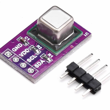
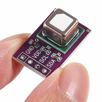
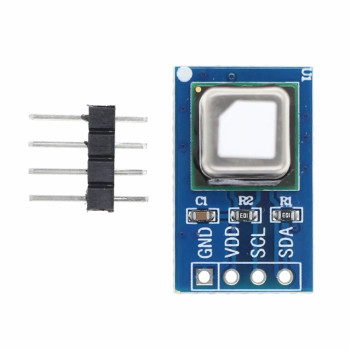
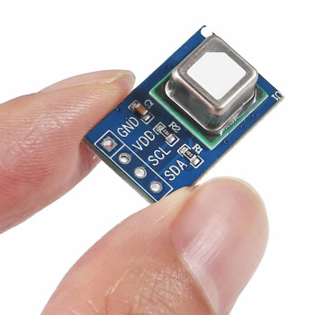
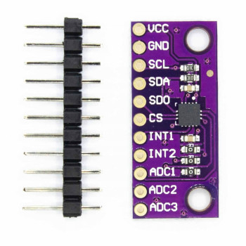
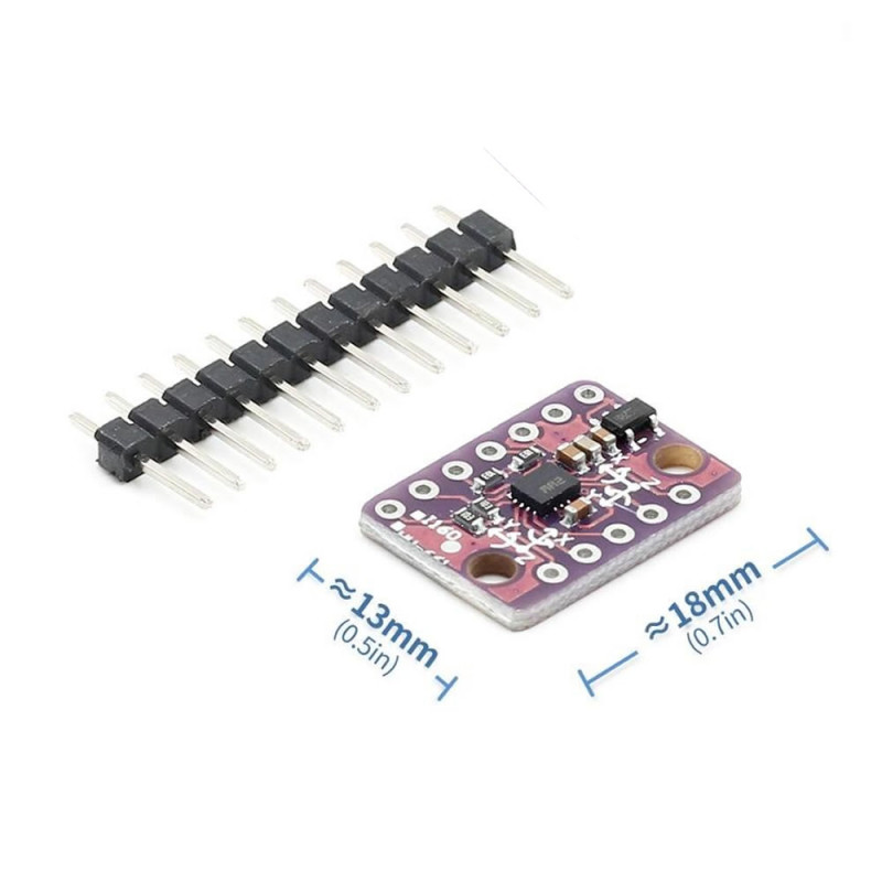
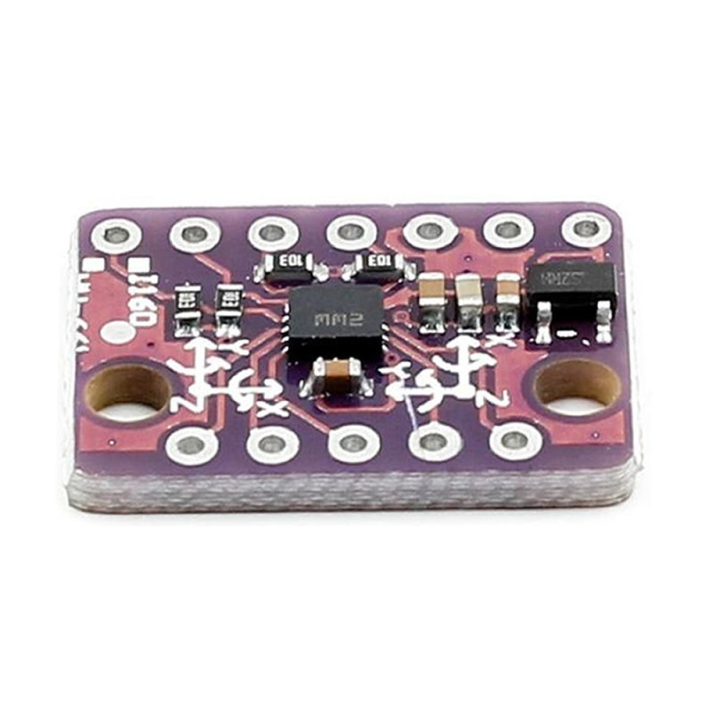
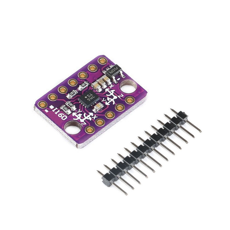
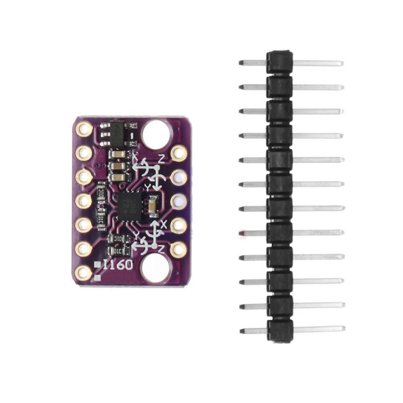
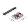
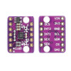
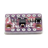
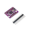
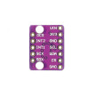
The BMI160 Gyro Sensor Module is a small purple board, known on the market as GY-BMI160, that uses Bosch's BMI160 6 axis (6DOF) motion sensor chip. The chip combines a 16 bit 3 axis accelerometer and a 3 axis gyroscope in one package. The module provides acceleration data (acceleration in the X, Y and Z directions) and gyroscope data (rotation speed around the X, Y and Z axes); it is used in projects that need tilt, orientation and motion detection.
With the accelerometer and gyroscope in full operation mode, the typical current consumption of the chip is only 925µA; thanks to this ultra low power consumption it is very suitable for battery powered IoT and wearable projects. Designed for smartphones, tablets and wearable devices, the BMI160 contains embedded functions such as a step detector and step counter (pedometer), significant motion detection, tap and orientation detection; movements such as running and walking are detected without extra processor load.
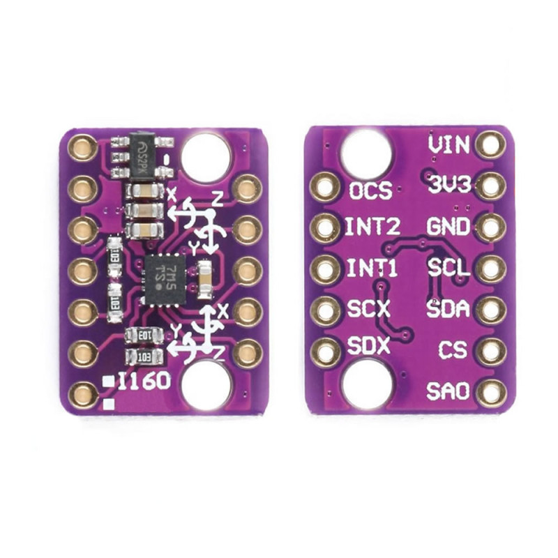
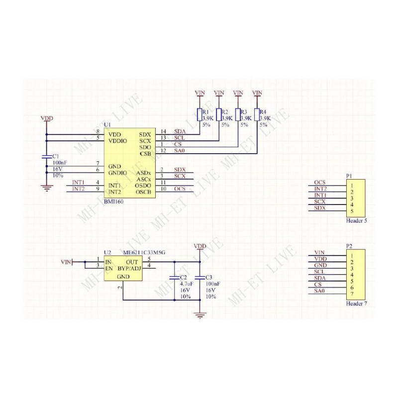
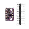
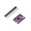
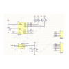
The module communicates over the I2C or SPI interface. Thanks to the LDO regulator on the board it can be powered with 3V-5V from the VIN pin; in 3.3V systems the 3V3 pin can be used directly. On the 12 pin board the power, I2C/SPI, address select (SAO) and two interrupt (INT1, INT2) pins are brought out. Thanks to the 2.54mm pin pitch it is easily tried on a breadboard; the board of about 18mm x 13mm is fixed to the project with screws through its 2 mounting holes.
Features:
- Sensor chip: Bosch BMI160, 3 axis accelerometer + 3 axis gyroscope (6DOF IMU)
- Accelerometer range: ±2g / ±4g / ±8g / ±16g (selectable)
- Gyroscope range: ±125 / ±250 / ±500 / ±1000 / ±2000 °/s (selectable)
- Resolution: 16 bit digital output (accelerometer and gyroscope)
- Communication interface: I2C (up to 1MHz) or SPI
- I2C address: 0x68 (SAO connected to GND) or 0x69 (SAO connected to 3.3V)
- Supply voltage: 3V-5V from the VIN pin (LDO regulator on board) or 3.3V from the 3V3 pin
- Signal level: 3.3V, no level shifter on the board (chip pins at most VDDIO+0.3V, VDDIO at most 3.6V)
- Current consumption: typical 925µA (accelerometer and gyroscope in full operation, chip value)
- Output data rate (ODR): accelerometer 12.5Hz - 1600Hz (in normal mode), gyroscope 25Hz - 3200Hz
- FIFO buffer: 1024 bytes (prevents data loss, the processor can sleep longer)
- Embedded functions: step detector and step counter, significant motion, any motion / no motion, tap, orientation and flat detection
- Interrupt outputs: INT1 and INT2, programmable
- Secondary interface: an external magnetometer (I2C) can be connected to the SCX / SDX pins for extension to 9 axes, or used as OIS (SPI, OCS chip select)
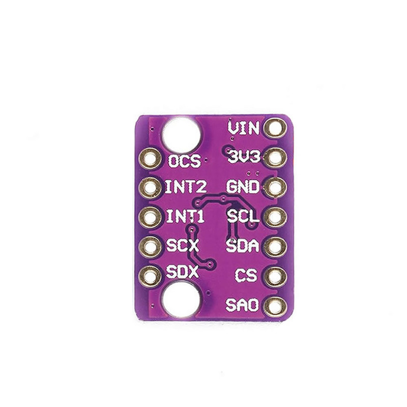
- Pins (12 pieces): VIN, 3V3, GND, SCL, SDA, CS, SAO, OCS, INT2, INT1, SCX, SDX
- Compatible boards: Arduino, ESP32, ESP8266, STM32, Raspberry Pi and all boards with I2C / SPI
- Shock resistance: 10000g (chip value)
- Operating temperature: -40°C - +85°C (chip value)
- Pin pitch: 2.54mm, breadboard compatible; 2 mounting holes
- Colour: Purple PCB
- Dimensions: about 18mm x 13mm
Usage information:
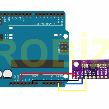
- I2C connection: connect VIN to 5V (or 3V3 to 3.3V), GND to GND, SCL to the SCL pin of the board and SDA to the SDA pin. If SAO is connected to GND the address is 0x68, if it is connected to 3.3V the address is 0x69; do not leave SAO floating.
- In I2C use, connect the CS pin to 3V3; in SPI use, CS is chip select, SCL is the clock (SCK), SDA is the data input (MOSI) and SAO is the data output (MISO).
- Set the I2C address in your software according to the SAO connection on your board (0x68 or 0x69). SCX and SDX are the clock and data pins of the chip's secondary interface (external magnetometer I2C or OIS SPI), and OCS is the chip select pin of the secondary OIS SPI interface; in basic use these three pins are left unconnected.
Areas of use:
- Drone and quadcopter flight controller boards
- Self balancing robots and vehicles
- Gimbal and camera stabilisation mechanisms
- Pedometer (walking step counting) and wearable devices
- Tilt measurement and digital spirit level
- Acceleration, vibration and free fall detection
- Displays switching between landscape / portrait mode
- Motion and gesture detection, air mouse applications
- VR / AR head tracking and game controllers
- Education and IoT projects with Arduino and ESP32
Precautions:
- The signal lines of the board are at 3.3V level and there is no level shifter on the board. With a 5V Arduino over I2C, a level shifter on the SCL / SDA lines is recommended; over SPI, the 5V outputs of the Arduino (CS, SCL, SDA) must not be connected to the board directly, use a level shifter.
- Do not apply 5V to the 3V3 pin; a 5V supply is connected only to the VIN pin. Do not apply more than 5V to VIN.
- When soldering the pin header, do not hold the soldering iron on the pin for a long time; the sensor chip is sensitive to heat and static electricity.
- Gyroscope data drifts over time. Before measuring, keep the module still and perform a zero point calibration; for the tilt angle, combine the accelerometer and gyroscope data with a filter (complementary / Kalman).
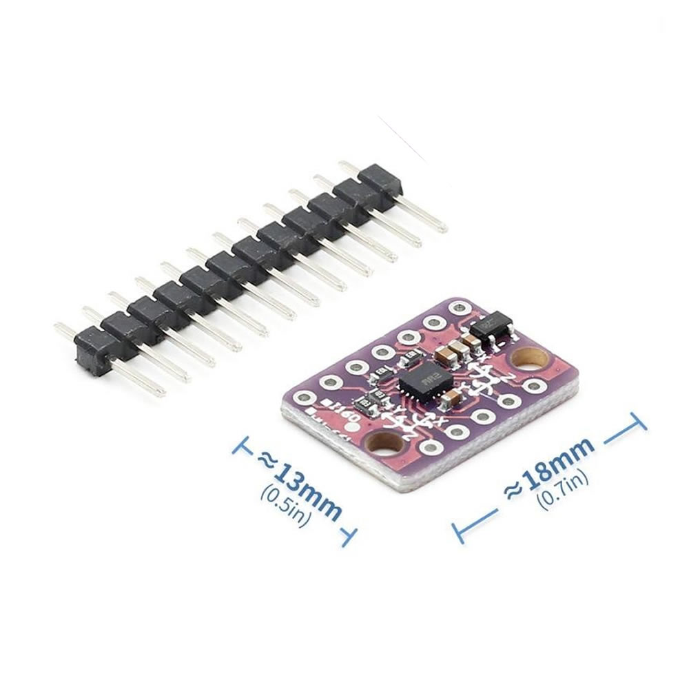
Package contents:
- 1 Piece BMI160 Gyro Sensor Module
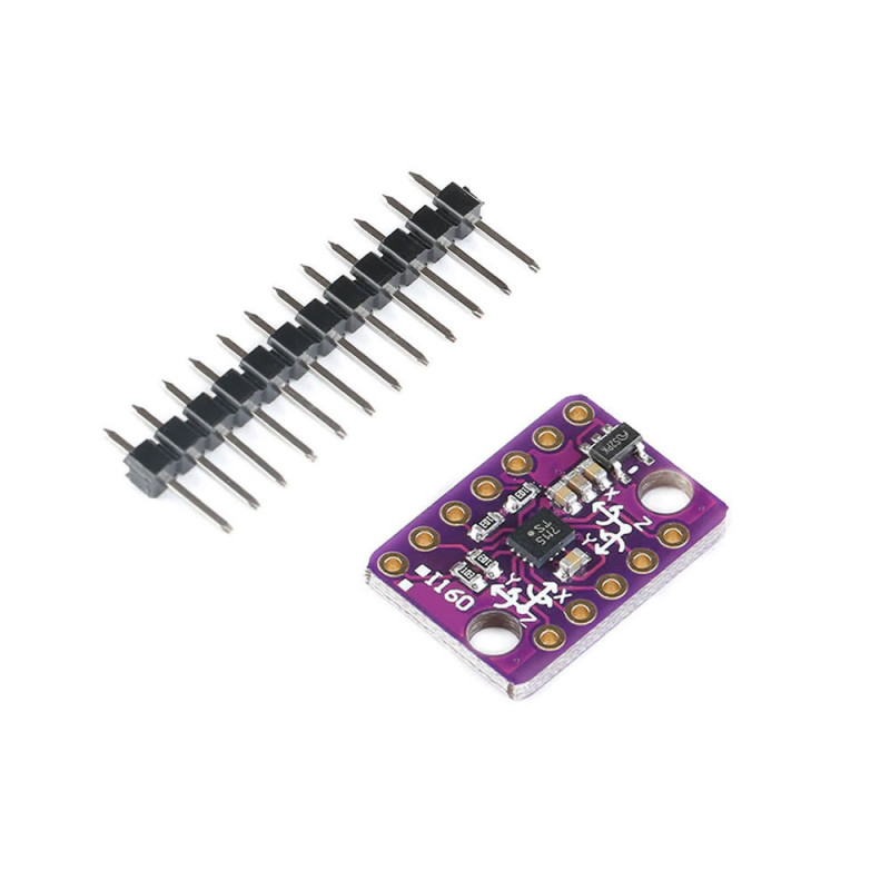
- 1 Piece 12 pin male pin header (not soldered)
- Note: Arduino / development board and connection cables are not included in the package.