Sepetim
Çerez kullanıyoruz 🍪
Sitemizin işlevselliğini ve tarama deneyiminizi geliştirmek için çerezler ve benzeri teknolojiler kullanıyoruz. Daha fazla bilgi için Gizlilik İlkesi sayfamızı inceleyebilirsiniz.
Saat 15:30'a kadar gelen siparişler aynı gün kargolanır
1100 TL üzeri Sürat Kargo ücretsiz
1500 TL üzeri Yurtiçi Kargo ücretsiz

FRM01 Time Relay

FRM01 Time Relay
FRM01 Time Relay
FRM01 Time Relay
FRM01 Time Relay
FRM01 Time Relay
FRM01 Time Relay
FRM01 Time Relay
FRM01 Time Relay
FRM01 Time Relay
FRM01 Time Relay
FRM01 Time Relay
FRM01 Time Relay
FRM01 Time Relay
FRM01 Time Relay
FRM01 Time Relay
FRM01 Time Relay
FRM01 Time Relay
403.20TL
Ex Tax: 336.00TL
  • Stok Durumu: Stok Var
  • Marka: OEM
  • Model: FRM01 Modül
  • SKU: RBZ.100.871


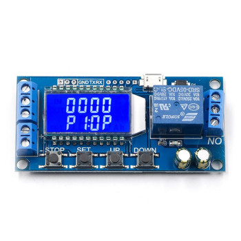
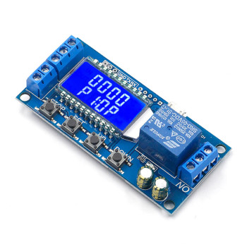
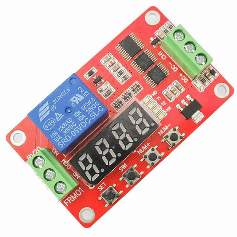
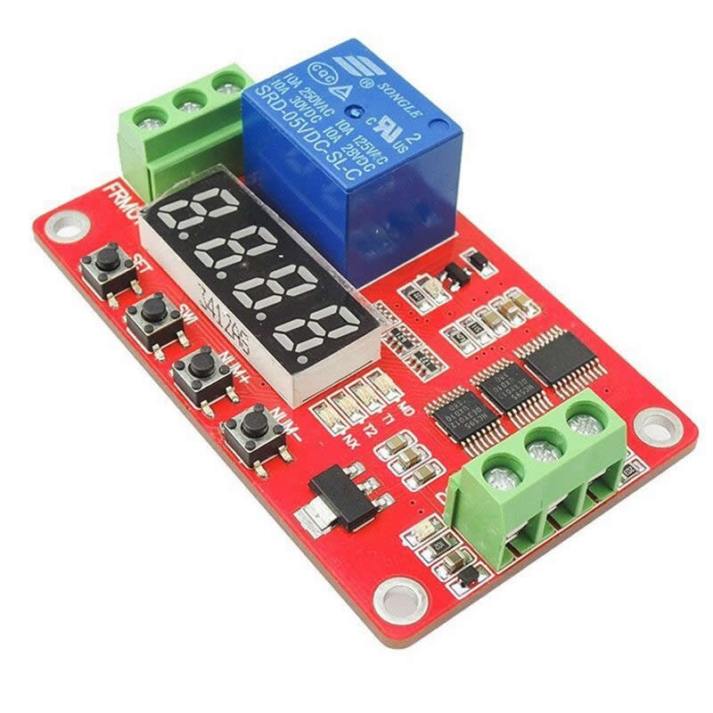
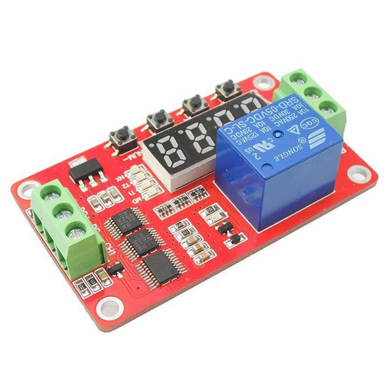
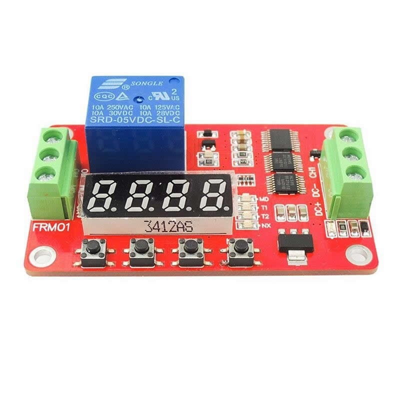
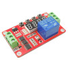
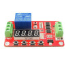
FRM01 Multifunction Time Relay


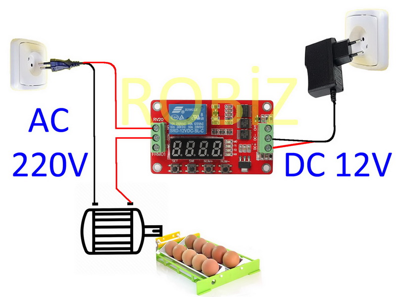
      This product is a time-based programmable relay module. It has 20 different ready-made programs. It is used in various time-based electronic control applications such as smart home, automatic control, incubator motor control .

      The module has a relay that can drive 220V 10A AC or 30V 10A DC loads. There are 2 time setting ( T1 - T2 ) menus on the device. T1 and T2  can be set to durations between 1-9999 seconds and 270 hours. A 12V-24V adapter can be used to power the device.
Product Usage:

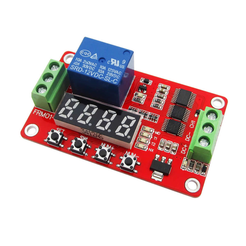
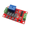
  •      If you press and hold the Set key, the function selection and programming menu is entered together with the MD led.
  •      You can select 20 different functions by setting the rightmost 2 digits of the screen with the ± keys. Using the ± keys, the numbers on the screen are increased and decreased.  You can make a selection between 01-20.
  •      SWI provides transition between the 4 digits of the screen.
  •      After selecting the program number, if the Set key is pressed briefly, the T1 T2 and NX menus are entered in order.
  •      T1: This is time setting number 1 to be used in the programs. You can make a setting between 0-9999 sec. Some programs use T1 values, some programs use T2 values. Some programs use both time settings. Both time settings may not have an effect in every program.
  •      T2: This is time setting number 2 to be used in the programs. You can make a setting between 0-9999 sec. Some programs use T1 values, some programs use T2 values. Some programs use both time settings. Both time settings may not have an effect in every program.
  •      NX: It is used to set the T1 and T2 durations to higher values in cases where the 9999 setting in seconds is not sufficient. It comes with the factory setting set as 0101. If you do not need higher durations, do not make a setting in this menu. It is used as a multiplier for T1 and T2. The first 2 digits of the Nx menu are the multiplier value for T1. The last 2 digits are the multiplier value for T2.
    • For example, if T1= 3000 and NX is 0101, the T1 operating time becomes 3000x01= 3000 sec. From the NX menu, these durations are increased by multiplying them as 2 digits each for t1 and t2.
    • For example, when T1= 1000 and T2: 2000 and NX is 0501 ; the T1 operating time becomes 1000x05= 5000 sec. T2= 2000x01= 2000 sec will be calculated.
    • In this way, the NX multipliers can be set to the highest values as 99   99. In a case where the timer value is also set to 9999 with a multiplier of 99, durations of up to 270 hours will have been set.
  •      If you press and hold the Set key, it exits the programming mode and the product starts to operate according to the settings. The settings you have made are saved to memory. After a power outage, the settings are read from memory and the relevant program starts to run with its initial values. The state the program had reached during the power outage is not recorded instantaneously. It is important that you know that in a power outage, the program you previously set will start from the beginning with its initial values.
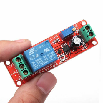
  •      There is a blue led next to the relay. If this led is on, it means the relay switch is active. A click sound is heard during the opening and closing of the relay switch. If the blue led is blinking but you cannot hear a sound from the relay, it means you are not powering the product with 12V. The device works with 5V but the relay switching on and off  operation only starts to occur after supplies of 9-10V.
  •      During the operation of the product, it cuts the power of the 4-digit indicator screen in order to reduce energy consumption. This does not mean that the product is not working. The durations continue to run in the background. The screen has been turned off only for energy saving. After the Set key is pressed briefly, the screen turns on immediately and the state of the program can be observed.


Product Technical Specifications:

  •     Operating voltage: DC 12V -24V
    •     The product also works with 5V. However, since the relay solenoid voltage is 12V, you need to power the product with an adapter of at least above 9V. For testing we applied voltage of up to 27V at the supply input. There was no problem in the operation of the product. We recommend that higher voltages not be applied. If the product has been damaged by you due to high voltage, it does not take us 5-10 sec to understand this.
  •     There is reverse connection protection on the adapter inputs. If power does not come when you make the connection, reverse the adapter cable ends and connect them.
  •     Operating current: 0.1A   ( Adapters are generally of high power capacity such as 1-2A. With a 1A adapter you can easily run 10 of this product..)
  •     Time Setting: 1sec - 274.9 hours
  •     Relay power:  0-30V/10A, AC 0-250V/10A
  •     Relay service life. 100000 times switching on and off
    •     If you create a program that will perform very short-term switching on and off, you may consume the life of the relay, which depends on its switching on and off, in a short time. If the relay on the product breaks down, your product will have become unusable.
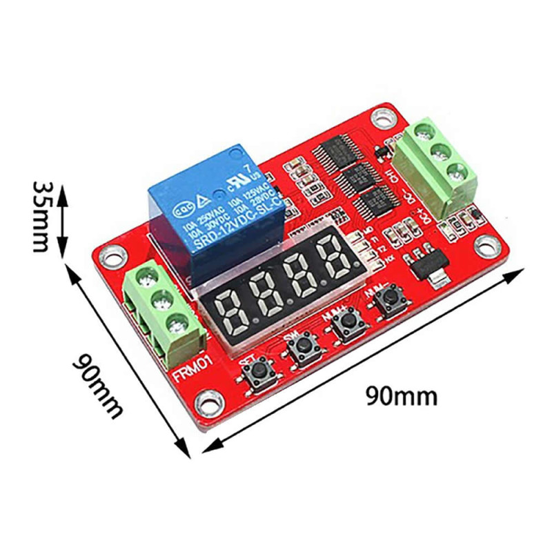
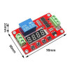
  •     Dimensions : 66mm x 41mm x 20mm
  •     4 Character 7 segment display
  •     4 Control and setting buttons


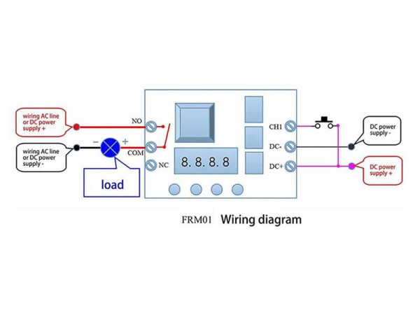
Input Terminal Connections:

  • DC+ : Supply + Terminal
  • DC-  : Supply – Terminal Ground
  • X1    : Signal Detection Input . An external signal can be read by connecting a button etc. ( Voltage between 3V-30V can be applied from the input) There is the possibility of running the device according to this external signal.


Relay Terminal Connections:  The common terminal (com) of the relay is switched between the open terminal and the closed terminal.

  •  NO    : Open Terminal
  •  COM : Common Terminal
  •  NC    : Closed Terminal


Functions:

  •         Timing Pick
  •         Timing off
  •         Timing pull off again
  •         Timing and then pull off
  •         Infinite loop timing mode 1
  •         Infinite loop timing mode 2
  •         Finite loop timing mode 1
  •         Finite loop timing mode 2
  •         Latching relay modes
  •         Trigger relay modes
  •         Pull the trigger timing
  •         Trigger timing off
  •         Pull the trigger timing then disconnect
  •         Disconnect and then pull the trigger timing
  •         Infinite loop timing mode 1
  •         Infinite loop timing mode 2
  •         Finite loop timing mode 1
  •         Finite loop timing mode 2
  •         Conditioned loop mode 1: Loop with signal, otherwise, loop stops
  •         Conditioned loop mode 2: Loop with signal, otherwise, loop stops


Function 6:  ( Infinite Loop Timing Mode 2) ( The program required for the motor rotation used in incubator use)
      The relay output is active for the duration of T1. When the T1 duration ends, the relay output turns off. It stays on standby for the duration of T2. When the T2 duration ends, the program returns to the beginning again and the relay output is active for the duration of T1. This loop continues constantly. If the power is cut and energy comes again, the program continues with the initial values.

In the future we can add the descriptions of the other functions according to needs.  We are adding a number of Turkish descriptions to the lower part. However, we have not researched the accuracy of these descriptions, which are quotations. We also did not examine whether there are errors in their translation into Turkish.


Package Contents:

  • 1 Piece FRM01 Time Relay


*********************************************


Power-on (start-up) delay function section:
 

Function 1 (timed out): When the power is on, the relay closes and after the delay time expires the relay is disconnected (the power always stays cut) and the duration is between 1 second and 999 seconds (or 1-999 minutes). Set a trigger signal to the reset interface or the IN interface (support high / low level trigger, external switch button trigger), interrupt the above functions and repeat;


Function 2 (timed pull-in): At start-up the relay is disconnected, after the delay time expires the relay closes (the power will stay off for a long time) and the duration is between 1 second and 999 seconds (or 1-999 minutes). Set a trigger signal to the reset interface or the IN interface (support high / low level trigger, external switch button trigger), interrupt the above functions and repeat;


Function 3 (timed pull-in and then disconnect): when the power is on the relay closes, the pull-in time (T1) can be set between 1 second and 999 seconds (or between 1-999 minutes) and the relay is disconnected after the end of the pull-in delay. The switching on, switching off time (T2) can be set between 1 second and 999 seconds (or 1-999 minutes) After the switch-off delay expires, the relay turns on again or gives a trigger signal to the IN interface. (Support high / low level trigger, external switch button trigger), interrupt the above functions midway and repeat;


Function 4 (Timed Disconnect and Pull-in): At start-up the relay is disconnected and the switch-off time (T1) can be set between 1 second and 999 seconds (or between 1-999 minutes). After the selection delay expires the relay is drawn in. The pull-in time (T2) can be set between 1 second and 999 seconds (or between 1-999 minutes). After the pull-in or delay time expires, the relay will stay on, such as switching on again or giving a trigger signal to the IN interface. (Support high / low level trigger, external switch button trigger), interrupt the above functions midway and repeat;


Loop timing function section  :


Function 5 (infinite loop timing mode 1): After being switched on the relay closes, the pull-in time (T1) can be set between 1 second and 999 seconds (or between 1-999 minutes) and after the delay expires the relay is disconnected. The switch-off time (T2) can be set between 1 second and 999 seconds (or between 1-999 minutes) After the switch-off delay ends, the relay presses the T1 key again for the infinite loop.  If the power is switched on again or a trigger signal is sent to the IN interface (supports high / low level triggering, external button triggering), the above functions can be interrupted once and repeated;


Function 6 (infinite loop timing mode 2): After being switched on the relay is disconnected, the switch-off time (T1) can be set between 1 second and 999 seconds (or between 1-999 minutes) and after the switch-off delay expires the relay closes. The pull-in time (T2) can be set between 1 second and 999 seconds (or 1-999 minutes) After the pull-in delay expires, the relay closes again with the T1 duration, thus looping infinitely.  If the power is switched on again or a trigger signal is sent to the IN interface (supports high / low level triggering, external button triggering), the above functions can be interrupted once and repeated;


Function 7 (Finite Loop Timing Mode 1): After being switched on the relay is energized, the pull-in time (T1) can be set between 1 second and 999 seconds (or between 1-999 minutes) and after the pull-in delay expires the relay is disconnected. The switch-off time (T2) can be set between 1 second and 999 seconds (or 1-999 minutes) After the switch-off delay expires, the relay is pressed again with the T1 time and the number of loops can be set between 1-999.  If the power is switched on again or a trigger signal is sent to the IN interface (supports high / low level triggering, external button triggering), the above functions can be interrupted once and repeated;


Function 8 (finite loop timing mode 2): After being switched on the relay is disconnected, the switch-off time (T1) can be set between 1 second and 999 seconds (or 1-999 minutes) and the relay closes after the end of the switch-off delay. The pull-in time (T2) can be set between 1 second and 999 seconds (or 1-999 minutes) After the pull-in delay expires, the relay closes again with the T1 duration and the number of loops can be set 1-999 times.  If the power is switched on again or a trigger signal is sent to the IN interface (supports high / low level triggering, external button triggering), the above functions can be interrupted once and repeated;


Trigger delay function section  :


Function 9 (trigger timing off 1): After being switched on, the relay does not act in the closed state, the IN interface waits for the trigger signal (supports high / low level trigger, supports external switch button trigger), when there is a trigger signal the relay pulls in. The pull-in time can be set between 1 second and 999 seconds (or 1-999 minutes) When the delay ends, the relay is disconnected and waits for the next trigger signal. The input interface trigger is invalid during the delay.


Function 10 (pull trigger timing 1): After being switched on, the relay does not operate in the closed state, the IN interface waits for the trigger signal (supports high / low level trigger, supports external switch button trigger), when there is a trigger signal, the relay stays In the disconnected state and delayed, the disconnection time can be set between 1 second and 999 seconds (or between 1-999 minutes), the delay has expired, the relay is closed (the power will always stay stuck), the next trigger signal is waited for The IN interface trigger is invalid during the delay.


Function 11 (trigger timing off 2): After being switched on, the relay is not acting in the closed state, the IN interface is waiting for the trigger signal (supports high / low level trigger, external switch button trigger), when there is a trigger signal the relay does not pull The pull-in time can be set from 1 second to 999 seconds (or between 1-999 minutes). When the delay ends, the relay is disconnected and waits for the next trigger signal IN-interface triggering is valid during the delay.


Function 12 (trigger timing 2 pull-in): After being switched on, the relay does not act in the closed state, the IN interface trigger signal is waited for (supporting high / low level trigger, supports external switch button trigger), when there is a trigger signal, the relay stays In the disconnected state and delayed, the disconnection time can be set between 1 second and 999 seconds (or between 1-999 minutes), the delay has expired, the relay is closed (the power will always stay stuck), the next trigger signal is waited for The IN interface trigger is valid during the delay.


Function 13 (trigger timing disconnects and sinks again 1): After being switched on the relay does not act in the closed state, the IN interface waits for the trigger signal (supports high / low level trigger, external switch button trigger) when there is a trigger signal the relay stays closed and delayed, the switch-off time (T1) can be set between 1 second and 999 seconds (or between 1-999 minutes), the relay is turned off after the disconnection delay and after the pull-in time (T2) ) can be set between 1 second and 999 seconds (or between 1-999 minutes), after the delay time expires the relay stays on.  Wait for the next trigger signal, the IN interface trigger is invalid during the delay.


Function 14 (trigger timing is engaged and then 1 disconnects): After being switched on the relay does not act in the closed state, the IN interface waits for the trigger signal (supports high / low level trigger, external switch button trigger), when there is a trigger signal the relay combined delay, the pull-in time (T1) can be set between 1 second - 999 seconds (or 1-999 minutes), after the pull-in delay expires the relay is disconnected, the switch-off time (T2) is 1. It can be set between seconds - 999 seconds (or 1-999 minutes), the relay will stay closed after the end of the switch-off delay.  Wait for the next trigger signal, the IN interface trigger is invalid during the delay.


Function 15 (trigger timing disconnects and sinks again 2): After being switched on the relay is not acting in the closed state, the IN interface is waiting for the trigger signal (supports high / low level trigger, external switch button trigger), when there is a trigger signal the relay stays closed and delayed, the switch-off time (T1) can be set between 1 second and 999 seconds (or between 1-999 minutes), the relay is turned off after the disconnection delay and after the pull-in time (T2) ) can be set between 1 second and 999 seconds (or between 1-999 minutes), after the delay time expires the relay stays on.  Wait for the next trigger signal, and the IN interface trigger is valid during the delay.


Function 16 (trigger timing is engaged and then 2 disconnects): After being switched on the relay does not act in the open state, the IN interface waits for the trigger signal (supports high / low level trigger, external switch button trigger) when there is a trigger signal the relay combined delay, the pull-in time (T1) can be set between 1 second - 999 seconds (or 1-999 minutes), after the pull-in delay expires the relay is disconnected, the switch-off time (T2) is 1. It can be set between seconds - 999 seconds (or 1-999 minutes), the relay will stay closed after the end of the switch-off delay.  Wait for the next trigger signal, and the IN interface trigger is valid during the delay.


Function 17 (self-latching relay function): When the IN interface has a trigger signal (supports high / low level trigger, external switch button trigger), the relay pulls in, then gives a signal, the relay is disconnected, press the Sel key 8 Analog test function


Function 18: (trigger relay function): When the IN interface has a trigger signal (supports high / low level triggering, external switch button trigger), the relay pulls in, the signal disappears and the relay is disconnected.


Be the first to write a review for this product.

Write a review

Note: HTML is not translated!
Bad           Good
Captcha
Marka: OEM
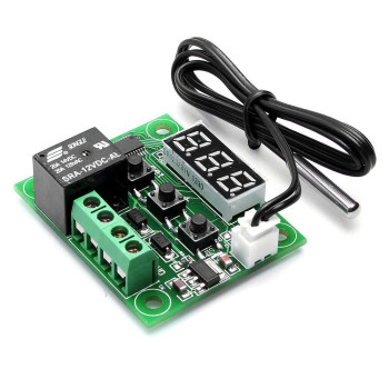
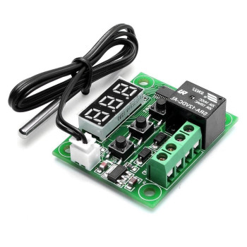
  Temperature Controlled Digital Thermostat W1209 Temperature Control Board Heater Cooler Incubator Aquarium Refrigerator Freezer Oven Boil..
115.20TL
Ex Tax:96.00TL
Add to Cart
Marka: OEM
  Mini Humidity Temperature Meter Display Digital Thermometer Incubator Greenhouse Warehouse Home Room Office Medical Panel Mount Box Do..
115.20TL
Ex Tax:96.00TL
Add to Cart
Marka: OEM
  9V Battery Adapter Converter Cable      It converts 9V batteries to a DC adapter socket. It allows supplying power throu..
11.52TL
Ex Tax:9.60TL
Add to Cart
Marka: OEM
  Panel Mount Type 2.1mm Adapter Socket DC-022 5.5mm x 2.1mm Plastic DC Power Socket   Features: 2.1mm/5.5mm DC Power Sock..
6.91TL
Ex Tax:5.76TL
Add to Cart
Marka: OEM
  XL4015 5A Adjustable Voltage Power Supply Module Steps Voltage Down 36V 5A DC DC Converter Step Down Power Module High Power High Efficie..
115.20TL
Ex Tax:96.00TL
Add to Cart
Marka: OEM
  MT3608 28V 2A DC Boost Module Adjustable Voltage Step Up Power Supply Step Up        It is a voltage step ..
46.08TL
Ex Tax:38.40TL
Add to Cart
Marka: OEM
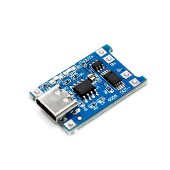
  TP4056 Battery Charging Board Protected Micro Usb Socket       This module is made with the TP4056 lipo charging c..
17.28TL
Ex Tax:14.40TL
Marka: OEM
  TP4056 Lipo Charging Module Mini usb TP4056 1A Li-ion Battery Charging Module      This module is made with th..
17.28TL
Ex Tax:14.40TL
Add to Cart