- Stok Durumu: Stok Var
- Marka: OEM
- SKU: RBZ.101.009
GY-511 LSM303DLHC 3 Axis Accelerometer 3 Axis Magnetometer Sensor Module
Compass 3V-5V I2C Magnetic Field Meter
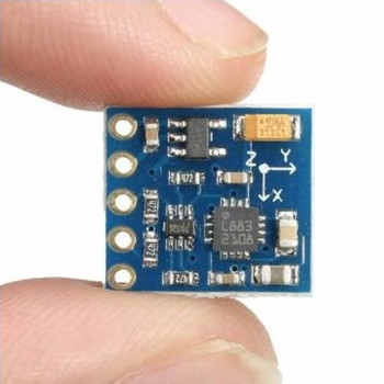
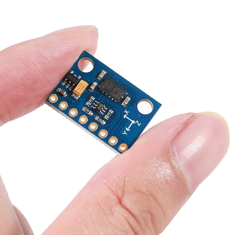
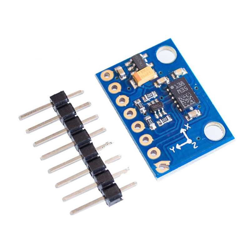
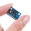
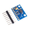
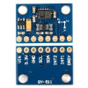
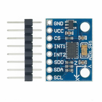
The GY-511 is a 3 axis accelerometer and 3 axis magnetometer (digital compass) module carrying the STMicroelectronics LSM303DLHC chip. Both sensors are in one chip and are read over the same I2C bus: the accelerometer has selectable ranges of ±2g, ±4g, ±8g and ±16g, the magnetometer from ±1.3 gauss to ±8.1 gauss; data is read from 16 bit registers with 12 bit resolution. The board measures 20.5mm x 14.5mm and weighs 2gr.
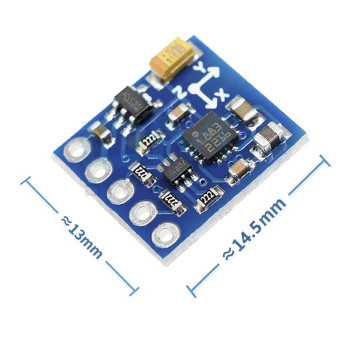
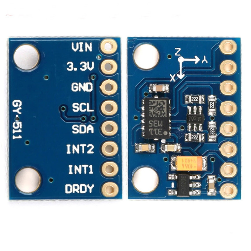
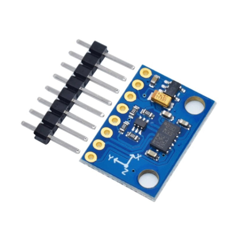
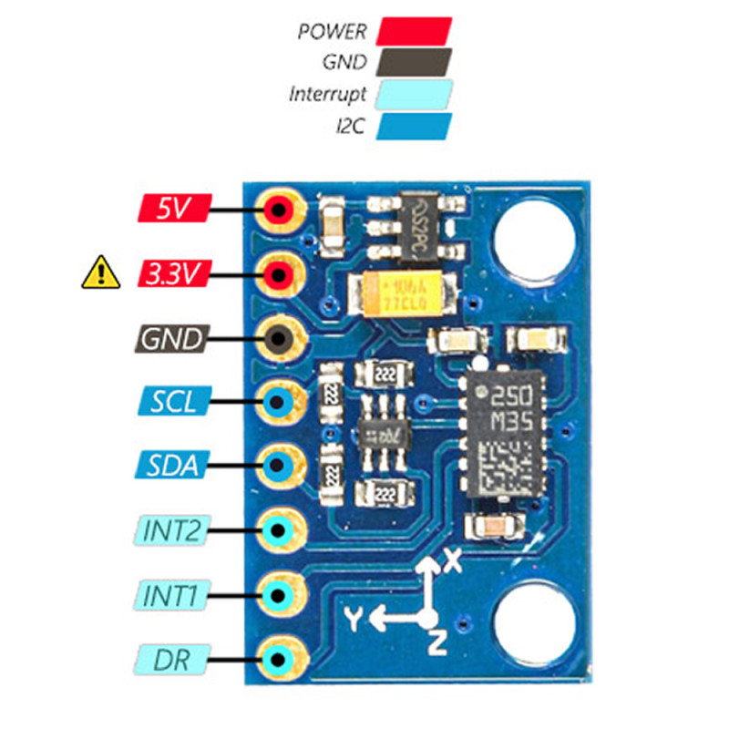
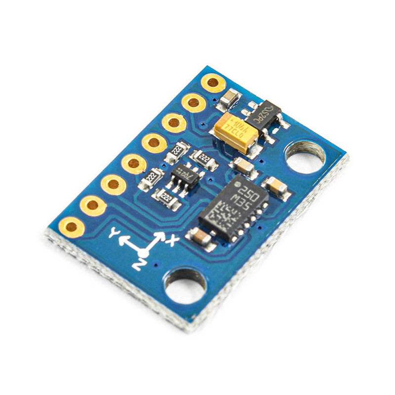
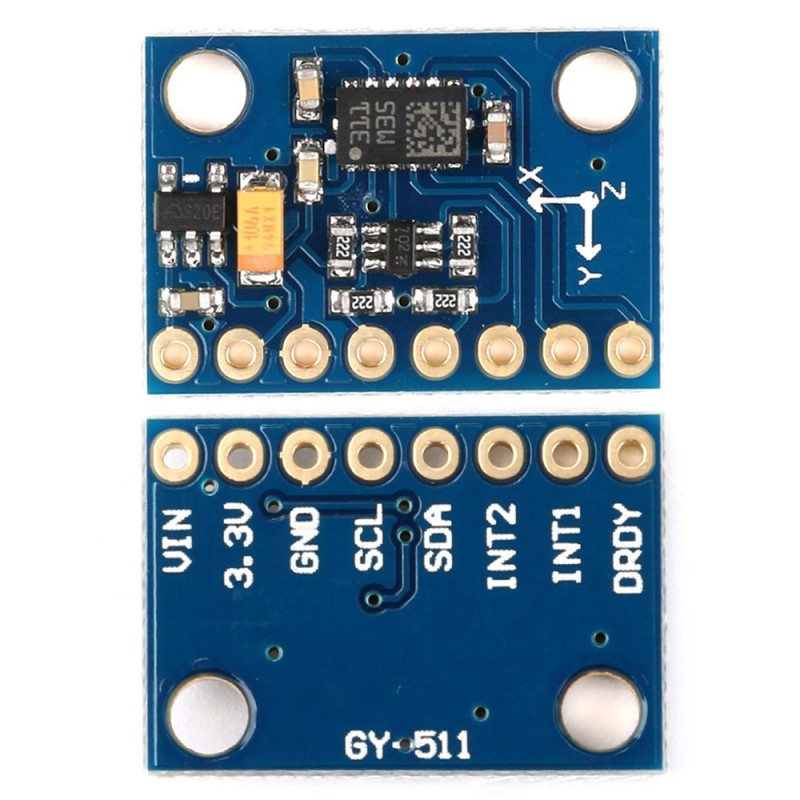
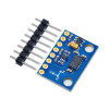
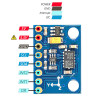
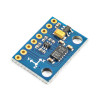
There is a 3.3V regulator on the board; the VIN pin is supplied with 3V - 5V, so the module can be used in both 3.3V and 5V systems. When 5V is applied, the 3.3V pin provides a 3.3V output for circuits drawing up to 100mA. The 8 pin 2.54mm pitch row has the VIN, 3.3V, GND, SCL, SDA, INT2, INT1 and DRDY pins; the X, Y, Z arrows on the board show the axis directions, and the board is fixed with two mounting holes.
The accelerometer measures the tilt of the board relative to gravity, the magnetometer measures the earth's magnetic field. Used together, a tilt-compensated heading can be calculated even when the board is not held level. It is therefore used in drone and robot heading, vehicle and boat navigation, qibla finding, tilt measurement, step counting and fall detection.
Key features:
Two sensors in one chip: The 3 axis accelerometer and 3 axis magnetometer are combined in the LSM303DLHC; on one I2C bus the accelerometer answers at 0x19 and the magnetometer at 0x1E.
Tilt-compensated compass: The magnetometer data is corrected with the tilt from the accelerometer, so the heading can be calculated even when the board is tilted.
3V - 5V supply: Thanks to the on-board 3.3V regulator, VIN accepts 3V - 5V; the 3.3V pin provides up to 100mA output.
Interrupt pins broken out: INT1, INT2 and DRDY are brought out to the header. The chip's 2 programmable interrupt generators report free-fall, motion and 6D/4D orientation change without constant polling by the processor.
Selectable range and rate: The accelerometer works at ±2g - ±16g with 1Hz - 1.344kHz data rate; the magnetometer at ±1.3 - ±8.1 gauss with 0.75Hz - 220Hz data rate.
Features:
- Product type: 3 axis accelerometer and 3 axis magnetometer (digital compass) module
- Model: GY-511
- Chip: STMicroelectronics LSM303DLHC
- Supply voltage (VIN): 3V - 5V
- On-board regulator: 3.3V; 3.3V output pin up to 100mA
- Interface: I2C, 100kHz and 400kHz
- I2C addresses: accelerometer 0x19, magnetometer 0x1E
- Accelerometer range: ±2g, ±4g, ±8g, ±16g (selectable)
- Magnetic field range: ±1.3, ±1.9, ±2.5, ±4.0, ±4.7, ±5.6, ±8.1 gauss (selectable)
- Data output: 16 bit registers, 12 bit resolution (magnetometer -2048 / +2047; accelerometer 1mg/LSB at ±2g)
- Accelerometer data rate: 1Hz - 1.344kHz (normal mode), up to 5.376kHz in low-power mode
- Magnetometer data rate: 0.75Hz - 220Hz
- Interrupts: 2 programmable interrupt generators (free-fall, motion), 6D/4D orientation detection, click / double-click recognition
- Built-in: temperature sensor and FIFO memory
- Chip current consumption: 110µA (normal mode, accelerometer at 50Hz and magnetometer at 7.5Hz data rate; board regulator excluded)
- Pins: VIN, 3.3V, GND, SCL, SDA, INT2, INT1, DRDY (8 pin, 2.54mm pitch)
- Operating temperature: -40°C - +85°C (LSM303DLHC)
- Color: Blue
- Dimensions: 20.5mm x 14.5mm
- Weight: 2gr
Pin description:
- VIN: Supply + (3V - 5V)
- 3.3V: 3.3V output pin when 5V is applied; for circuits drawing up to 100mA
- GND: Supply - (ground)
- SCL: I2C clock
- SDA: I2C data
- INT2: Interrupt 2
- INT1: Interrupt 1
- DRDY: Magnetometer data ready
Usage information:
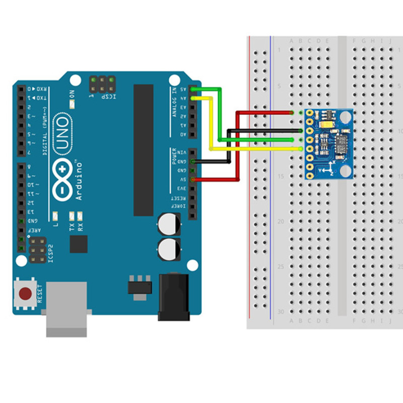
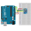
- Connect VIN to the 5V or 3.3V supply of the controller board, GND to GND, and SDA and SCL to the I2C pins of the board. An I2C scan shows the two addresses of the module (0x19 and 0x1E).
- With ready libraries that support the LSM303DLHC (e.g. Pololu LSM303), acceleration and magnetic field values are read directly; range and data rate are selected in software.
- Calibrate the magnetometer before using it as a compass: rotate the module a full turn on every axis at its final mounting place, record the minimum and maximum of each axis and subtract their average as offset.
- The axis directions are shown by the X, Y, Z arrows on the board; place the module according to these arrows relative to the front of your device.
Application areas:
- Drone and quadcopter heading (compass) and tilt information
- Robot and autonomous vehicle navigation
- Boat and vehicle heading indicators
- Qibla finding and digital compass applications
- Pedometers and motion tracking devices
- Fall detection and impact warning systems
- Tilt and angle measurement (digital spirit level)
- Antenna and solar panel orientation
- Motion activated devices (click / double-click, shake detection)
Points to consider:
- The magnetometer is affected by nearby iron, magnets, motors, speakers and high current cables. Place the module away from them and calibrate at the final mounting place.
- The compass shows magnetic north; for geographic (true) north take the magnetic declination of your location into account.
- The 3.3V pin is an output pin and supplies up to 100mA; power is applied to the VIN pin.
- The LSM303DLHC has no gyroscope; if angular rate is needed during fast turns, a sensor module with a gyroscope is required.
Package contents:
- 1 pcs GY-511 LSM303DLHC Module