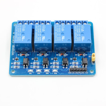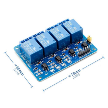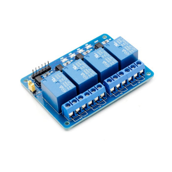

- Stok Durumu: Stok Var
- Marka: OEM
- SKU: RBZ.100.582
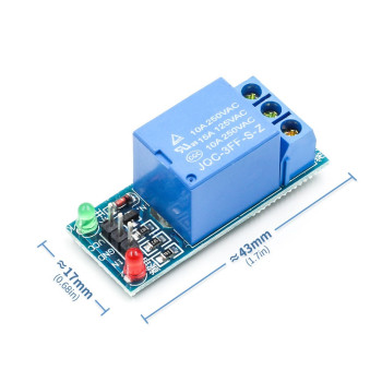
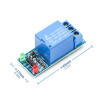
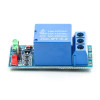
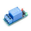
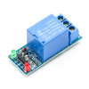
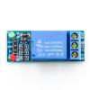
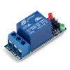
1 Channel 12V Relay Module
Battery Adapter Powered Control Board Caravan Boat Lamp Fan Pump Solenoid Valve Irrigation Greenhouse Aquarium Door Lock Alarm Contactor
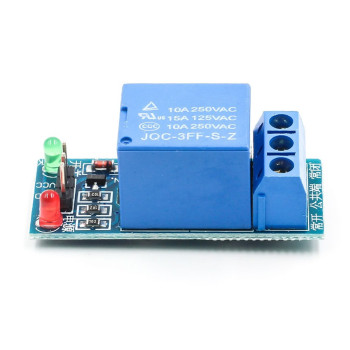
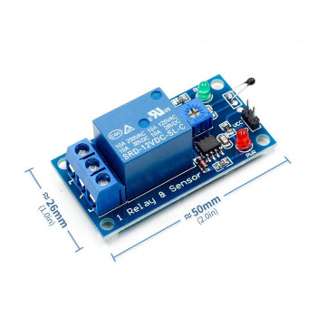
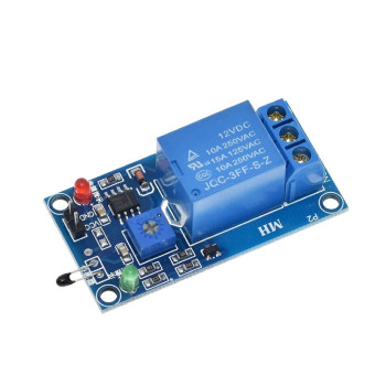
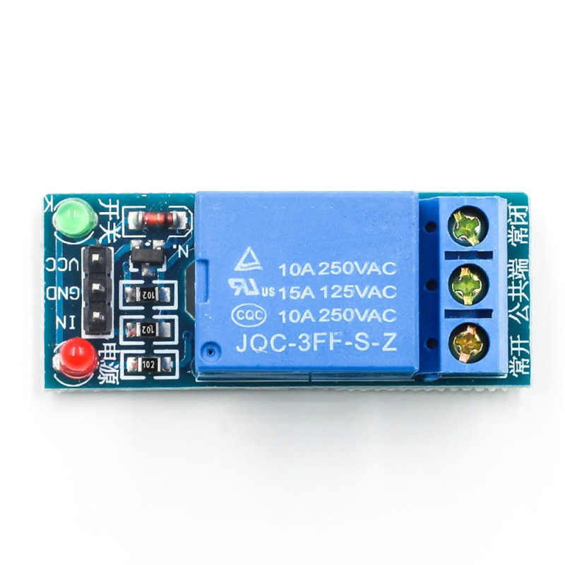
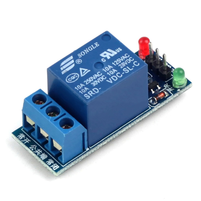
The 12V 1 channel relay module is a ready relay board that runs on a 12V supply and switches loads up to 250VAC or 30VDC with a low current control signal. The board carries a JQC-3FF-S-Z relay with a 12V coil, a transistor circuit that drives the relay coil, a coil protection diode and two status LEDs. The current needed by the relay coil is supplied by the driver circuit on the board, not by the control pin; the IN pin draws about 4mA.
The supply of the board (VCC) is 12V; therefore it is used with a 12V adapter, a 12V battery or in 12V electrical systems such as caravans and boats without needing a separate 5V supply. The control input can be driven directly with TTL logic level signals. The 12V relay coil draws about 30mA and the relay operates in about 10ms and releases in 5ms.
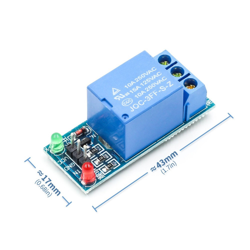
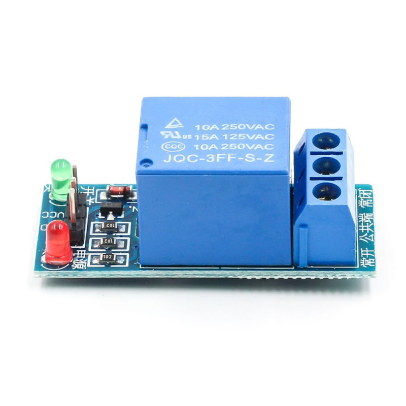
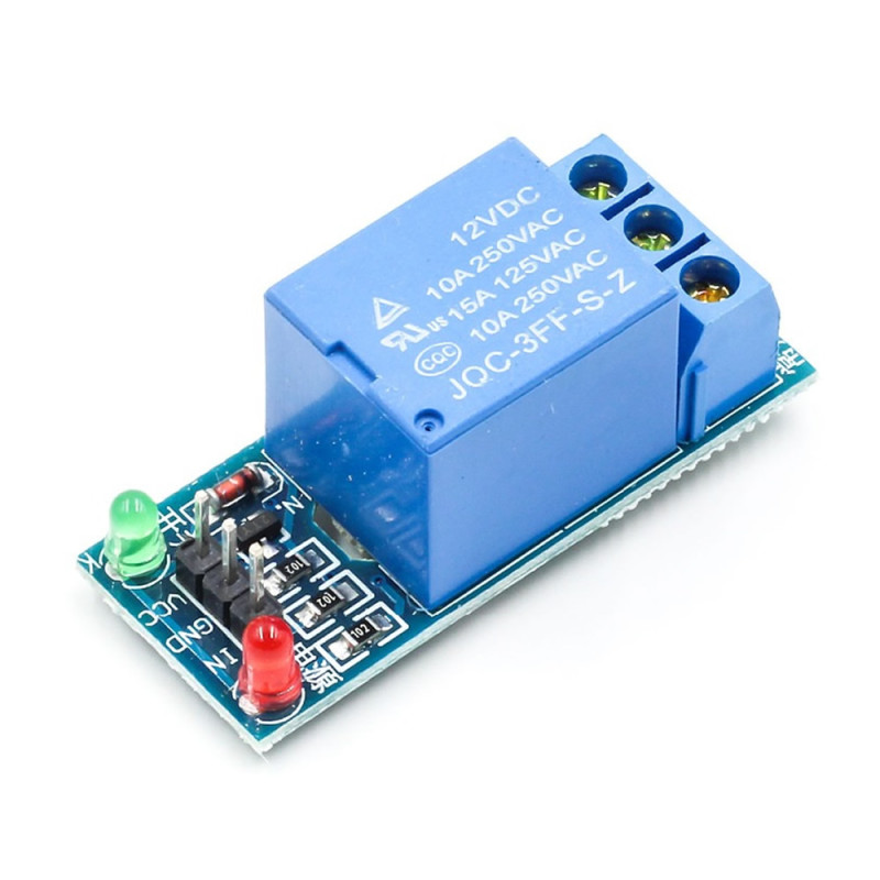
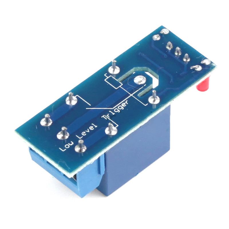
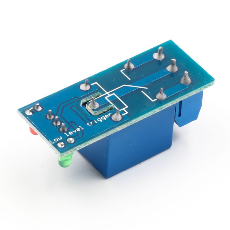
The NO (normally open), COM (common) and NC (normally closed) terminals of the relay are brought out to a 3-way screw terminal; loads such as a lamp, fan, pump, solenoid valve or contactor coil are connected without soldering. The control side is connected with a 3-pin male pin header: VCC, GND and IN. The board of about 43mm x 17mm fits easily in narrow boxes and control panels.
Key features:
12V supply: The relay coil is 12V. In systems powered by a 12V adapter or battery it runs from the same line; this is the difference from the 5V relay module.
10A contact rating: The contacts of the JQC-3FF-S-Z relay are rated 10A 250VAC and 10A 30VDC; with the single changeover contact (NO - COM - NC) the load can be wired to run or to stop when the relay operates.
Low control current: The IN pin draws about 4mA. The transistor on the board supplies the about 30mA current of the relay coil, so the control output is not loaded.
Screw terminal connection: The load terminals are brought out to a 3-way screw terminal and the control lines to a 3-pin header; the board is connected without soldering.
Status LEDs: The power LED shows that the board is powered and the relay output LED shows that the relay is operated; this helps during installation and troubleshooting.
Features:
- Product type: 1 channel 12V relay module
- Relay: JQC-3FF-S-Z, 12V coil, single changeover contact (NO - COM - NC)
- Supply (VCC): 12V
- Contact rating (AC): 10A 250VAC (also 15A 125VAC printed on the relay)
- Contact rating (DC): 10A 30VDC
- Control input (IN): can be driven directly with TTL logic level signals
- Input current: the IN pin draws about 4mA
- Relay coil: 12V, about 30mA (400Ω, 0.36W)
- Relay operate voltage: at most 9V (75% of the coil voltage); the relay does not operate on a 5V supply
- Relay operate / release time: about 10ms / 5ms
- Compatible boards: control boards with a digital output such as Arduino, 8051, AVR, PIC, ARM, MSP430
- Contact insulation: The relay contacts are insulated from the coil (relay rating 1500VAC). The board has no optocoupler; it does not provide additional safety isolation between the control circuit and the mains.
- Coil protection diode: Protects the driver circuit against the reverse voltage generated when the relay releases.
- Status LEDs: 2 pcs; power LED and relay output indicator LED
- Control connection: 3-pin male pin header (VCC, GND, IN)
- Load connection: 3-way screw terminal (NO, COM, NC)
- Colour: Blue relay, blue terminal
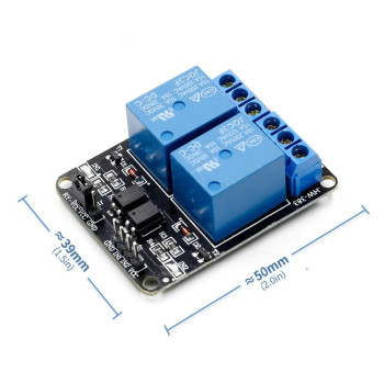
- Dimensions: about 43mm x 17mm x 18mm
- Weight: about 15gr
Usage information:
- Connect the VCC pin to the 12V supply, the GND pin to the GND of both the supply and the control board, and the IN pin to the digital output pin you will control. The GND of the control board and the relay module must be common.
- Connect the load that must run when the relay operates between COM and NO, and the load that must stop when the relay operates between COM and NC.
- After completing the connections, switch the relay on and off by changing the level of the output pin; the relay output LED shows the state of the relay.
- In systems powered by a 12V battery (caravan, boat) take VCC from a fused line; connect the load to the relay contact over a separate fused line.
Areas of use:
- Home automation powered by a 12V adapter; lamp, socket and lighting control
- Switching loads in caravan and boat 12V electrical systems
- Fan, water pump and solenoid valve control
- Greenhouse, garden irrigation and aquarium automation
- Timer, thermostat and humidity control circuits
- Door lock, garage door and bell triggering
- Driving sirens and warning lamps in alarm and security systems
- Controlling large loads by driving a contactor coil
- Battery, charging and power cut-off circuits
- Load control in 12V solar energy systems
Precautions:
- This board is 12V powered. If it is supplied with 5V the relay does not operate; use a 5V relay module for 5V powered systems.
- When working with 220V mains voltage, make the connections with the power off. Use the board inside an insulating box so that the terminals and solder points cannot be touched.
- The 10A 250VAC and 10A 30VDC values are upper limits. With inductive loads with high inrush current such as motors and compressors, work with a lower current or drive a contactor with the relay.
- There is no optocoupler on the board; the GND of the control board and the relay module are connected together. Do not apply the 12V supply to the pins of the control board.
Package contents:
- 1 Piece 12V 1 Channel Relay Module
- Note: The 12V adapter and connection cables are not included in the package.