- Stok Durumu: Stok Var
- Marka: OEM
- SKU: RBZ.100.322
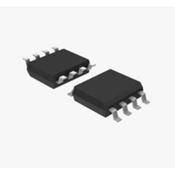
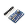
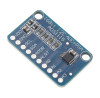
ADS1115 ADC PGA Module
16 Bit I2C ADS1115 4 Channel ADC PGA Programmable Gain Amplifier
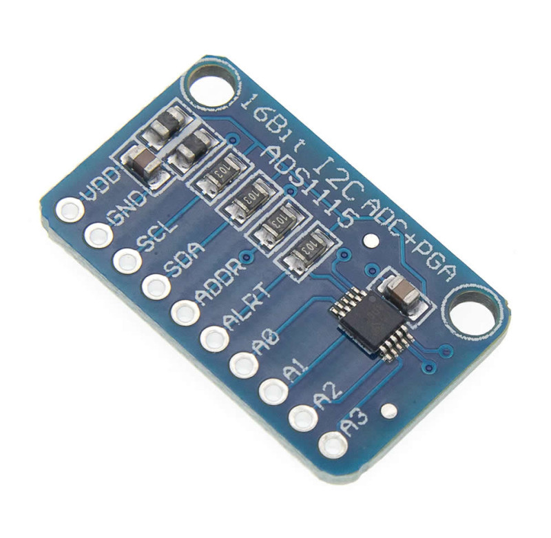
The ADS1115 ADC Module is an analog to digital converter board that measures 4 analog inputs with 16 bit resolution using the ADS1115 IC and outputs the result over the I2C bus. The inputs are used as 4 single-ended channels (A0, A1, A2, A3) or 2 differential channels (A0-A1, A2-A3). The sample rate is selectable between 8SPS and 860SPS. Thanks to the internal programmable gain amplifier (PGA), the full scale range is set in 6 steps from ±6.144V down to ±0.256V; on the most sensitive range one step is about 7.8µV, so small mV level signals can also be measured.
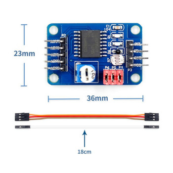
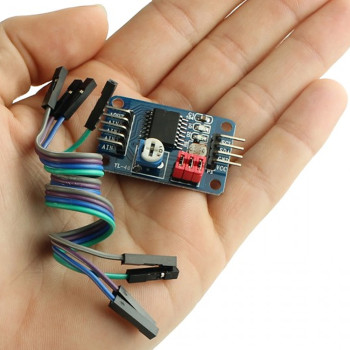
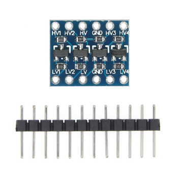
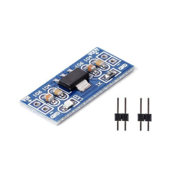
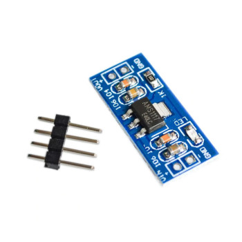
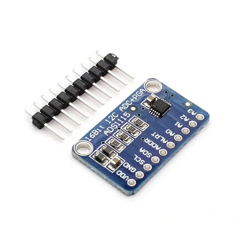
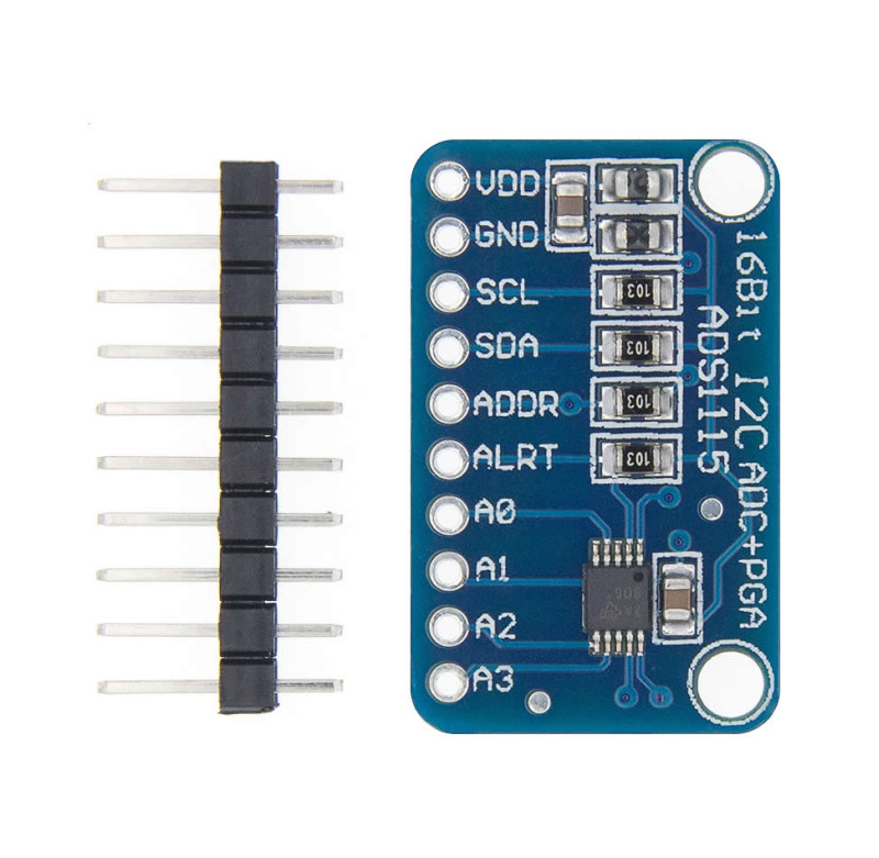
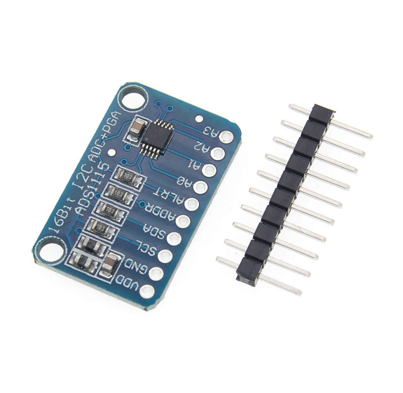
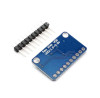
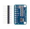
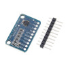
The module is powered from 2.0V - 5.5V and works the same way in 3.3V and 5V systems. It draws about 150µA in continuous mode, and in single-shot mode it goes to sleep automatically after each conversion; it suits battery powered devices. The ADDR pin selects one of 4 I2C addresses (0x48 - 0x4B), so 4 modules can be connected to the same I2C bus for 16 single-ended inputs. One edge of the board carries 10 pins: VDD, GND, SCL, SDA, ADDR, ALRT, A0, A1, A2, A3; a 10-pin male pin header comes loose (unsoldered) in the package. The board has 2 mounting holes.
Key features:
16 bit resolution: Measures with much finer steps than the 10 bit or 12 bit ADC on many controller boards; on the most sensitive range one step is about 7.8µV.
Programmable gain (PGA): Full scale ranges of ±6.144V, ±4.096V, ±2.048V, ±1.024V, ±0.512V and ±0.256V are selected in software; a small signal is amplified and measured over the full range.
Single-ended or differential input: 4 separate voltages can be measured against GND, or the difference between two points such as a shunt resistor or a bridge sensor is measured with 2 differential channels.
4 modules on one bus: Connecting the ADDR pin to GND, VDD, SDA or SCL selects one of the addresses 0x48, 0x49, 0x4A, 0x4B; 16 inputs are used on a single I2C bus.
Comparator and ALRT output: The ALRT pin signals when a set threshold is exceeded or a conversion is complete; the controller can use this pin as an interrupt instead of polling.
Features:
- Product type: 16 bit 4 channel I2C ADC module
- Model: ADS1115 ADC Module
- IC: ADS1115
- Resolution: 16 bit (15 bit in single-ended measurement due to the sign bit)
- Input channels: 4 single-ended (A0, A1, A2, A3) or 2 differential (A0-A1, A2-A3)
- Sample rate: 8SPS - 860SPS, programmable
- PGA full scale ranges: ±6.144V, ±4.096V, ±2.048V, ±1.024V, ±0.512V, ±0.256V
- Smallest step (LSB): 187.5µV (±6.144V) - 7.8µV (±0.256V)
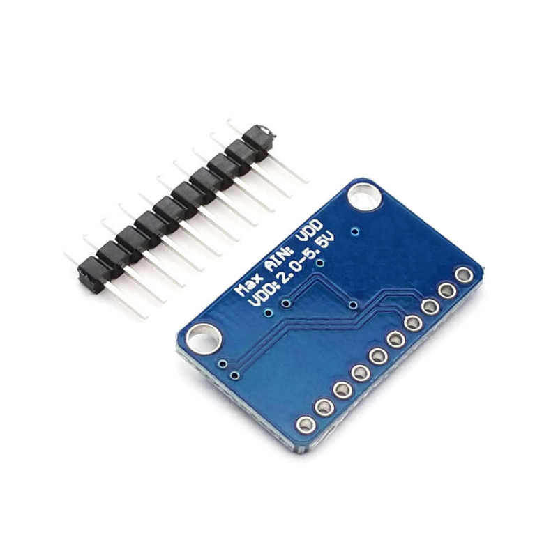
- Supply voltage: 2.0V - 5.5V
- Analog input voltage: Between GND and VDD (max. VDD + 0.3V)
- Current consumption: About 150µA in continuous mode; automatic sleep after conversion in single-shot mode
- Interface: I2C
- I2C address: 0x48 (ADDR - GND, default), 0x49 (ADDR - VDD), 0x4A (ADDR - SDA), 0x4B (ADDR - SCL)
- Internal blocks: Low drift voltage reference, oscillator, PGA, comparator
- ALRT pin: Threshold exceeded or conversion ready signal
- On-board resistors: ADDR pulled to GND with 10k (address 0x48 when left open), ALRT pulled up with 10k
- Pins: VDD, GND, SCL, SDA, ADDR, ALRT, A0, A1, A2, A3 (10 pins, 2.54mm pitch)
- Mounting: 2 mounting holes
- Operating temperature: -40°C - +125°C (ADS1115 IC rating)
- Colour: Blue board, white print
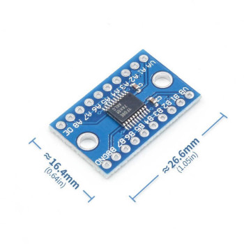
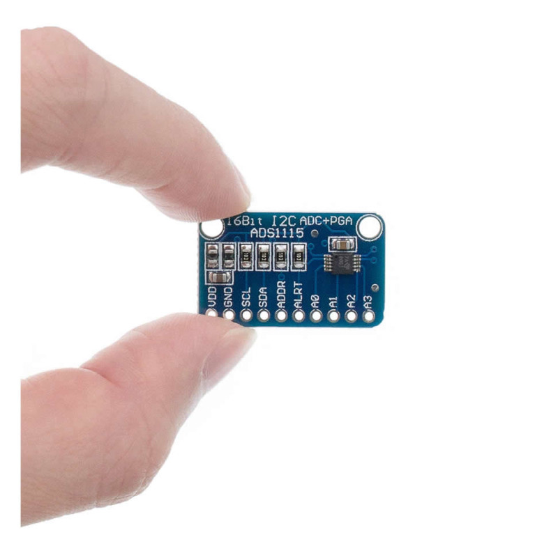
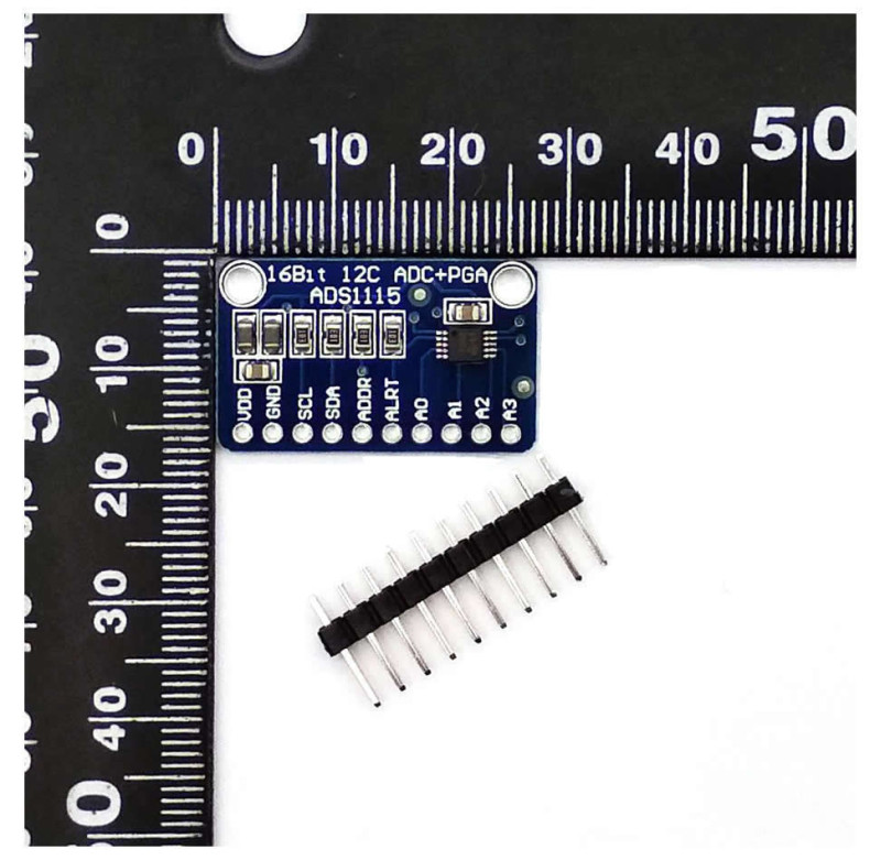
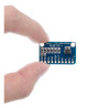
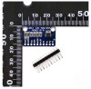
- Dimensions: Approx. 28mm x 18mm
Usage information:
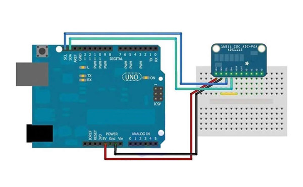
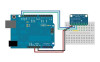
- Connect VDD to the logic voltage of your controller board (3.3V or 5V), GND to GND, and SCL and SDA to the I2C pins of the controller. If ADDR is left open, the address is 0x48.
- Connect the voltage to be measured to inputs A0 - A3. Whatever PGA range is selected, the voltage applied to the input must stay between GND and VDD; even with the ±6.144V range, a voltage higher than VDD cannot be measured.
- Measure higher voltages (e.g. a 12V battery) by bringing them below VDD with a resistor voltage divider; for current measurement, connect the two ends of a shunt resistor to a differential input (A0-A1) and select a small PGA range.
- If you use more than one module, separate the addresses by connecting the ADDR pin of each module to a different point (GND, VDD, SDA, SCL).
Applications:
- Precision voltage measurement and digital voltmeters
- Battery voltage monitoring
- Current measurement with a shunt resistor
- mV level signals such as scales (load cells) and bridge type sensors
- Temperature measurement (NTC, PT100 bridge, analog temperature sensor)
- Analog sensor reading (pressure, light, humidity, gas, potentiometer)
- Data logging and measuring devices
- Threshold comparator and alarm circuits
- Adding analog inputs to controller boards without an ADC or with a limited ADC (Arduino, ESP32, ESP8266, Raspberry Pi)
- Portable instruments, factory automation and process control
Precautions:
- Do not apply voltages below GND (lower than -0.3V) or above VDD + 0.3V to the analog inputs; the IC will be damaged. A negative voltage cannot be applied directly to an input even in differential mode.
- The PGA range is the full scale value, not the input limit; even with ±6.144V selected the input cannot exceed VDD.
- The maximum sample rate is 860SPS; it is not suitable for sampling audio or fast changing signals.
- A load cell (scale) signal is very small: a 10mV signal is measured with only about 1280 steps even on the most sensitive range (±0.256V). For precise weighing a 24 bit load cell converter (such as the HX711) is more suitable.
- Modules on the same I2C bus must have different addresses; if two modules share an address, neither reads correctly.
- For precise measurement keep analog wires short and connect the sensor GND to the module GND; a noisy supply causes fluctuation in the last bits.
Package contents:
- 1 Piece ADS1115 ADC Module
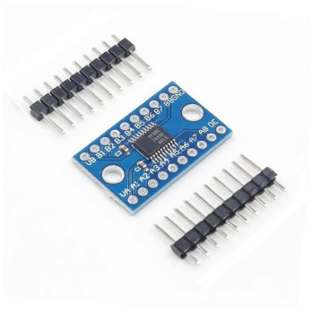
- 1 Piece 10-pin male pin header (unsoldered)
- Note: Controller board, sensor and connection wires are not included in the package.