- Stok Durumu: Stok Var
- Marka: STMicroelectronics
- SKU: RBZ.200.071
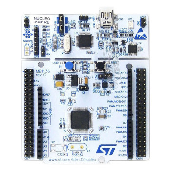
St NUCLEO-F767ZI NUCLEO F767ZI
STM32F767ZI Development Kit ST-LINK V2 32 Bit ARM Cortex M7 216MHz 2 MB Flash 512KB SRAM Arduino
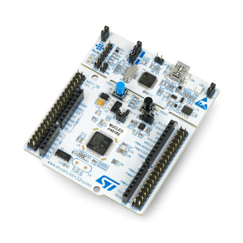
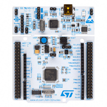
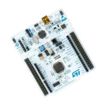
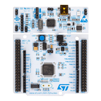
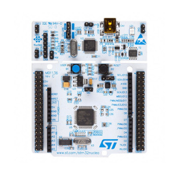
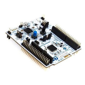
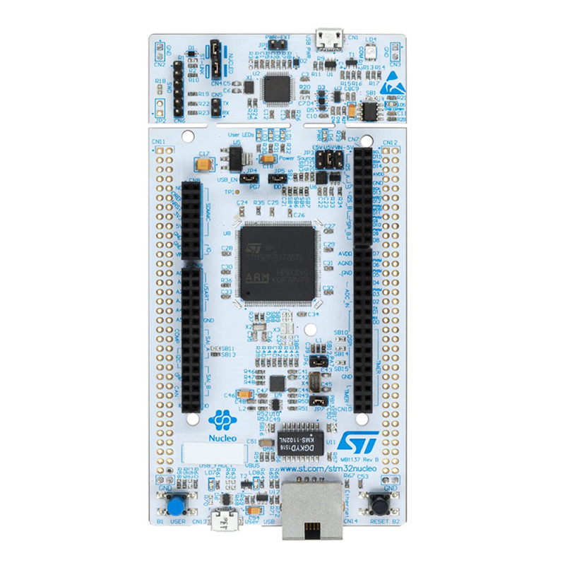
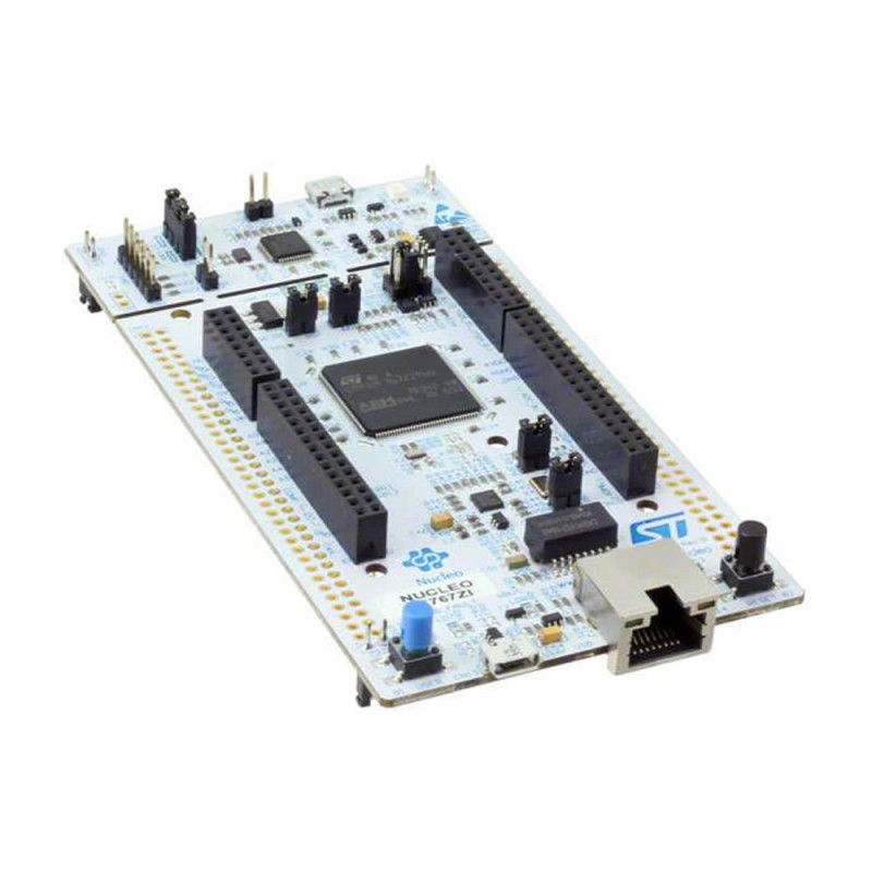
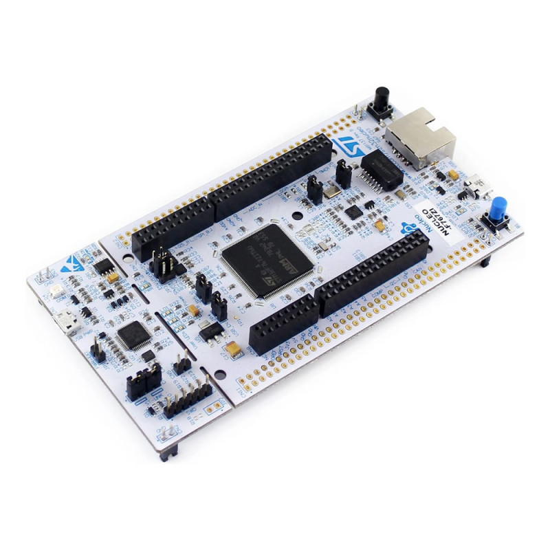
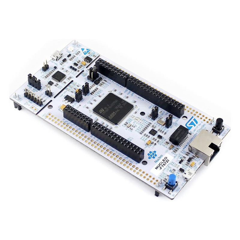
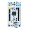
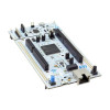
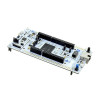
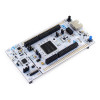
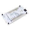
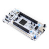
NUCLEO-F767ZI is the original STM32 Nucleo-144 development board from STMicroelectronics (MB1137). It carries the STM32F767ZIT6 microcontroller in an LQFP144 package: Arm Cortex-M7 core with double precision FPU, 216MHz clock, 2MB Flash and 512KB RAM. This member of the STM32F7 family has a Chrom-ART graphics accelerator, hardware JPEG codec, LCD-TFT controller and camera interface; it is a strong base for display devices, image and audio processing trials.
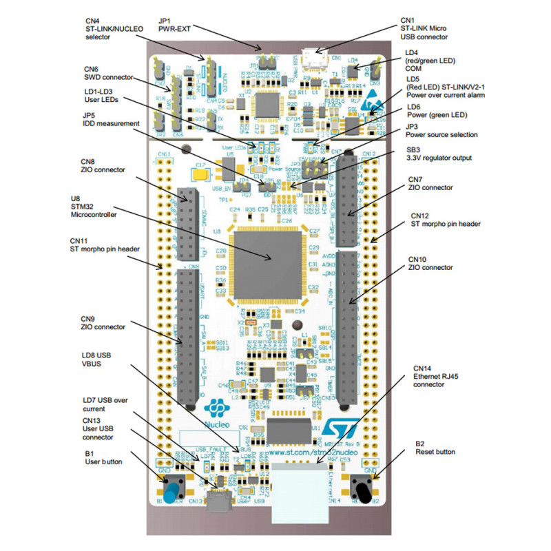
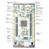
At the bottom edge of the board there is a 10/100 Ethernet connection with an RJ45 socket and a USB OTG port with a Micro-AB connector; the board is ready for wired networking and USB device / host applications without an extra module. The ST-LINK/V2-1 programmer and debugger at the top needs no separate device: when connected to a computer with a Micro USB cable it appears as a virtual COM port, a USB drive for drag-and-drop programming and a debug port. With its selection jumpers it can also be used as a standalone ST-LINK/V2-1 that programs another STM32 board over the SWD connector.
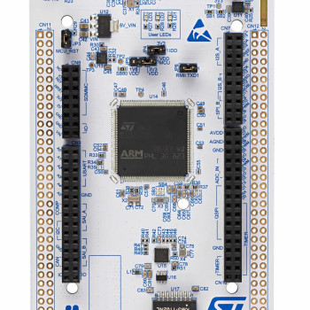
The ST Zio connector extends the Arduino Uno V3 layout; shields plug in directly. The ST morpho pin rows on both sides give access to all I/O pins of the microcontroller. The board can be powered from the ST-LINK USB (5V), with 7V - 12V on the VIN pin of Zio / morpho, or with external 5V on the E5V pin of morpho; the 5V source is selected with the JP3 jumper. It is supported by STM32CubeIDE, Keil MDK, IAR EWARM, GCC based toolchains and the STM32Cube HAL examples.
Key features:
216MHz Cortex-M7: STM32F767ZI with double precision FPU; with 2MB Flash and 512KB RAM (including 128KB DTCM) it handles fast control loops, signal processing and graphical interface work.
Ethernet and USB on board: 10/100 Ethernet with RJ45 socket and Micro-AB USB OTG; gateway, web server and USB device trials are done without an extra board.
Image and audio units: Chrom-ART accelerator, hardware JPEG codec, LCD-TFT controller up to XGA resolution, camera interface, SAI and I2S audio interfaces.
ST-LINK/V2-1: On-board programmer and debugger; virtual COM port, USB drive and debug port work over the same Micro USB cable, and it can be used as a standalone ST-LINK when needed.
Zio and morpho expansion: The Arduino Uno V3 compatible Zio connector takes shields, the morpho pin rows give access to all STM32 I/O pins.
Features:
- Product type: STM32 Nucleo-144 development board (original STMicroelectronics, MB1137)
- Model: NUCLEO-F767ZI
- Microcontroller: STM32F767ZIT6, LQFP144 package, VDD 1.7V - 3.6V
- Core and speed: Arm Cortex-M7, double precision FPU, up to 216MHz
- Memory: 2MB Flash, 512KB RAM (including 128KB DTCM), plus 16KB ITCM RAM and 4KB backup SRAM
- Graphics and image: Chrom-ART accelerator, hardware JPEG codec, LCD-TFT controller up to XGA resolution, camera interface
- Ethernet: IEEE 802.3 compliant 10/100 Ethernet MAC, RJ45 socket on board
- USB: USB OTG HS (High Speed needs an external ULPI PHY, not on the board) and USB OTG FS; Micro-AB user USB connector on board working at Full Speed (USB OTG)
- Communication: CAN, 6 SPI, 4 I2C, 3 I2S, 4 USART, 4 UART, 2 SAI, SPDIFRX, HDMI-CEC, dual mode Quad SPI, SDMMC
- Analog: 3 x 12-bit ADC (24 channels, 2.4MSPS), 2 channel 12-bit DAC
- Timers: 2 x 32-bit and 12 x 16-bit timers, 2 of them motor control PWM timers, plus 1 low-power timer
- Security: true random number generator (RNG)
- Debugger: On-board ST-LINK/V2-1 (Micro USB) and SWD connector; virtual COM port, USB drive (drag-and-drop programming), debug port; standalone ST-LINK mode
- Expansion: ST Zio connector (Arduino Uno V3 compatible, A0 - A5, D0 - D15) and ST morpho pin rows
- Power: ST-LINK USB VBUS 5V (U5V), 7V - 12V on the VIN pin (Zio / morpho), 4.75V - 5.25V on the E5V pin (morpho); selected with the JP3 jumper. Direct supply from the 3.3V pin only when the ST-LINK is disabled (SB3 and SB111 open)
- Indicators and buttons: 3 user LEDs (LD1 green, LD2 blue, LD3 red), ST-LINK COM LED (LD4), green power LED (LD6), red overcurrent LED (LD5); blue USER and black RESET button
- Clock source: 32.768kHz crystal (for RTC), 8MHz clock from ST-LINK (HSE)
- Software support: STM32CubeIDE, Keil MDK, IAR EWARM, GCC based toolchains, STM32Cube HAL and examples, Zephyr
- Color: White PCB
- Weight: approx. 122gr (with box)
Usage information:
- For first use leave the JP3 jumper in the U5V position and connect the board to the computer from the ST-LINK Micro USB port at the top. The power LED and COM LED light up; the board appears on the computer as a USB drive and a virtual COM port.
- Dragging a compiled .bin file onto the USB drive programs the board. For debugging, ST-LINK is selected in STM32CubeIDE, Keil or IAR; the ST-LINK firmware is updated with STM32CubeProgrammer.
- For Ethernet a network cable is plugged into the RJ45 socket; with the LwIP examples in the STM32CubeF7 package the board is ready for ping, web server and TCP/UDP trials over the network. The Micro-AB USB port at the bottom is for USB device or host applications; it is not for programming and does not power the board. The board must be powered before a cable is plugged into this port.
- When USB power is not enough, move JP3 to the VIN position and apply 7V - 12V to the VIN pin, or in the E5V position apply 5V to the E5V pin. Order: first JP3, then the external supply, last the ST-LINK USB cable.
Application areas:
- Ethernet gateway, web server and Modbus TCP devices
- Vehicle and machine control applications with CAN communication
- Motor control and driver applications with PWM timers
- Image processing with camera interface and JPEG codec
- Audio processing and digital audio applications with SAI / I2S
- User interface and graphic panel trials with LCD-TFT display
- IoT and remote monitoring devices
- Datalogger and data recording to memory card with SDMMC
- Learning STM32F7 and Arm Cortex-M7 at university and in the lab
Things to consider:
- No USB cable is included in the package. A USB-A / Micro-B cable is needed separately to connect the board to a computer.
- The I/O pins of the microcontroller are at 3.3V level. Before connecting a sensor or module with 5V output directly to the pins, check in the datasheet whether the pin is 5V tolerant.
- Do not apply more than 12V to the VIN input. The current available from VIN drops as the voltage rises: 800mA at 7V, 250mA between 9V and 12V. Set the JP3 jumper to the correct position before changing the power source; do not power the board from two sources at the same time.
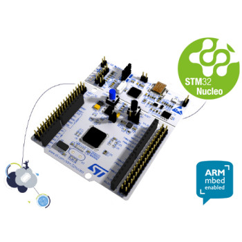
- The Arm Mbed platform mentioned in older listings was sunset in July 2026; according to Arm, Mbed projects can no longer be built with the online tools. Use STM32CubeIDE or Zephyr for new projects.
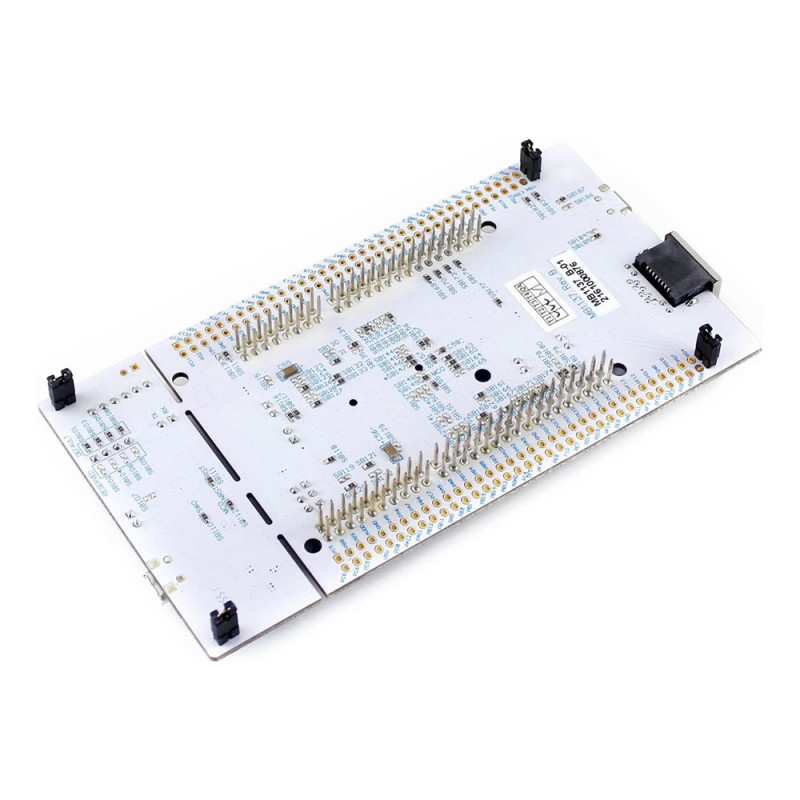
- Do not place the board on a conductive surface; the solder points on the bottom can short. Hold the board by its edges against static electricity.
Package contents:
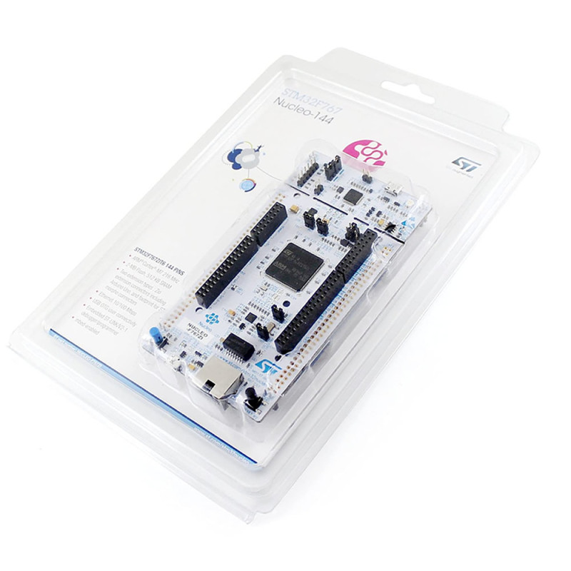
- 1 x NUCLEO-F767ZI Development Board
- Note: USB cable is not included in the package.