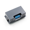
- Stok Durumu: Stok Var
- Marka: OEM
- SKU: RBZ.100.365
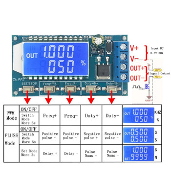
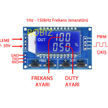
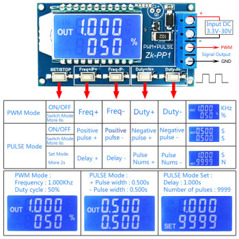
1Hz-150KHz XY-PWM1 PWM Signal Generator
Frequency and Duty Adjustable Square Wave Pwm Signal Generator
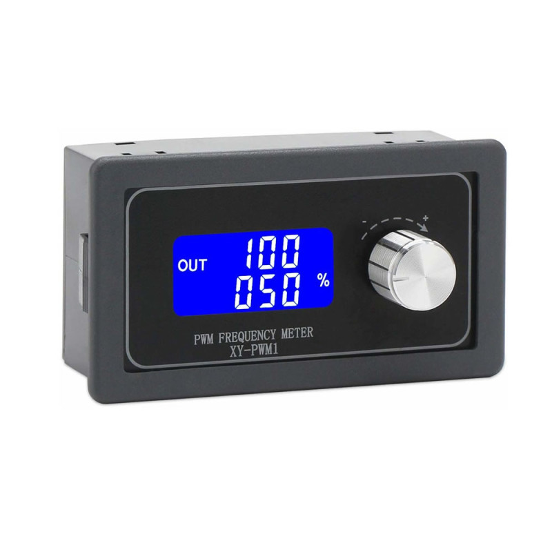
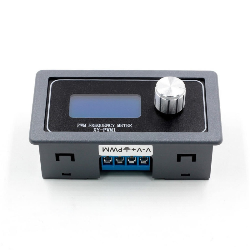
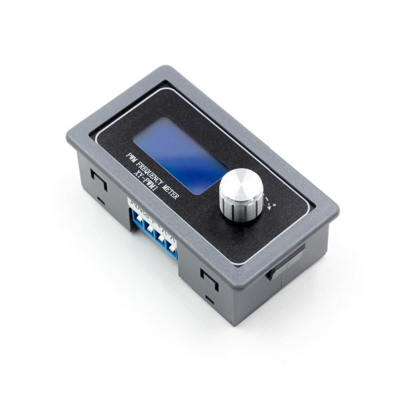
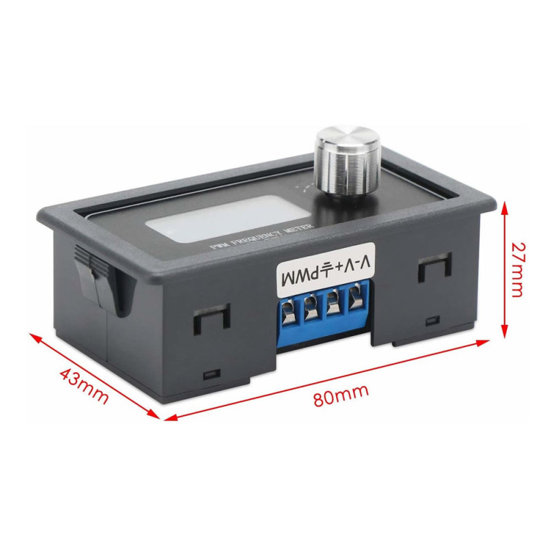
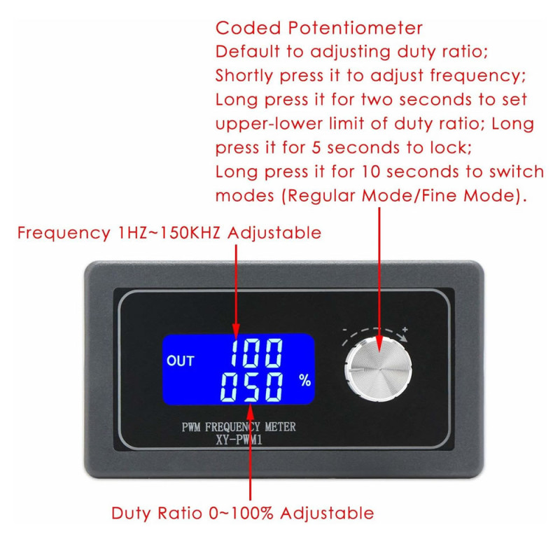
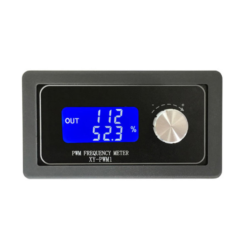
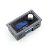
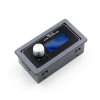
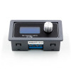
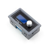
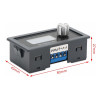
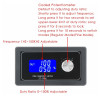
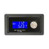
The XY-PWM1 Signal Generator Module is a panel type signal generator with LCD display and case that produces a square wave PWM signal with frequency adjustable between 1Hz - 150kHz and duty cycle between %0 - %100. It operates between DC 3.3V-30V. The upper line of the display shows the frequency, the lower line the duty cycle (%); all settings are made with the push rotary knob on the front panel. Its dimensions are 78mm x 43mm x 37mm and it weighs 42gr.
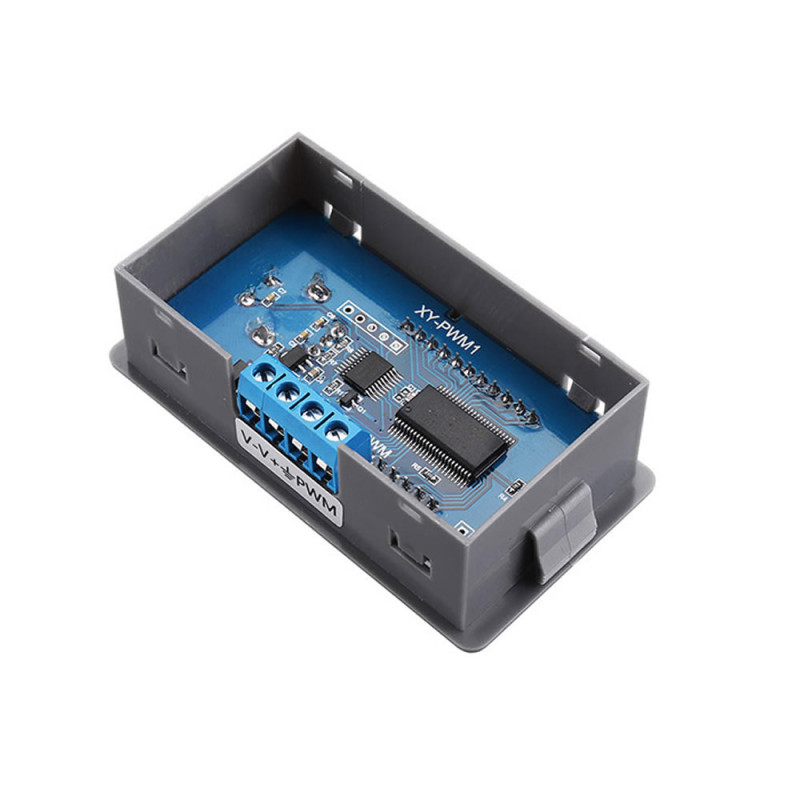
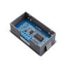
There are two operating modes: in normal mode the frequency is set between 1Hz - 150kHz and the duty cycle in %1 steps; in precise mode the frequency is set between 1Hz - 15kHz and the duty cycle in %0.1 steps. The frequency accuracy is about %2. Settings can be locked; while locked, touching the knob by accident does not change the value. Settings are saved in the module memory, and when power returns after an outage the module keeps producing the signal with the last setting. Inside the case there are TTL UART communication pins for digital control from an external device.
It is a signal output with an output current of about 5mA - 30mA; it controls motors, fans and LEDs not directly but through the PWM input of a motor driver, MOSFET or dimmer board. It is used as an adjustable PWM source for motor speed control, fan speed setting, LED brightness setting, servo and driver board testing; thanks to its panel case it can be mounted on the front panel of a device.
Key features:
Wide frequency range: The frequency is set between 1Hz - 150kHz in normal mode and 1Hz - 15kHz in precise mode; the same module covers everything from a slow trigger signal to high frequency PWM.
Fine duty cycle setting: The duty cycle is set between %0 - %100 in %1 steps in normal mode and %0.1 steps in precise mode; LED brightness and motor speed are changed in small steps.
LCD display and single knob: The backlit LCD shows frequency and duty cycle at the same time. Settings are made with the push rotary knob; after setting, the knob is locked to prevent the value from changing by accident.
Setting memory: The last settings are saved in the module memory; after a power outage the module continues with the same frequency and duty cycle.
Wide supply and panel case: It works with a DC 3.3V-30V supply; the panel type case mounts on a device front panel. The TTL UART pins inside the case allow digital control from an external device.
Features:
- Product type: Panel type PWM square wave signal generator with LCD display
- Model: XY-PWM1
- Frequency range (normal mode): 1Hz - 150kHz
- Frequency range (precise mode): 1Hz - 15kHz
- Frequency accuracy: approx. %2
- Duty cycle range: %0 - %100
- Duty cycle step: %1 in normal mode, %0.1 in precise mode
- Operating voltage: DC 3.3V - 30V
- Output signal: Square wave PWM; amplitude approx. equal to the supply voltage
- Output current: approx. 5mA - 30mA
- Display: Backlit LCD; frequency and duty cycle (%) shown at the same time
- Adjustment: Push rotary knob
- Setting lock: Yes; while locked the knob does not change the value
- Setting memory: Yes; last setting kept when power is off
- Communication: TTL UART pins (inside the case)
- Operating temperature: -20°C - 70°C
- Material: Plastic panel type case
- Colour: Dark grey case, blue LCD display
- Dimensions: 78mm x 43mm x 37mm
- Weight: 42gr
Usage information:
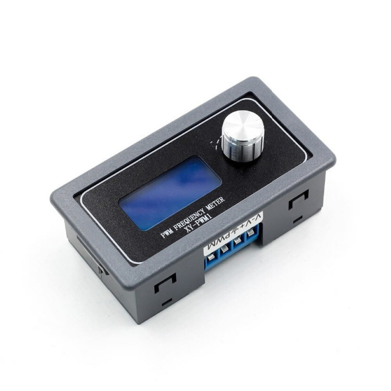
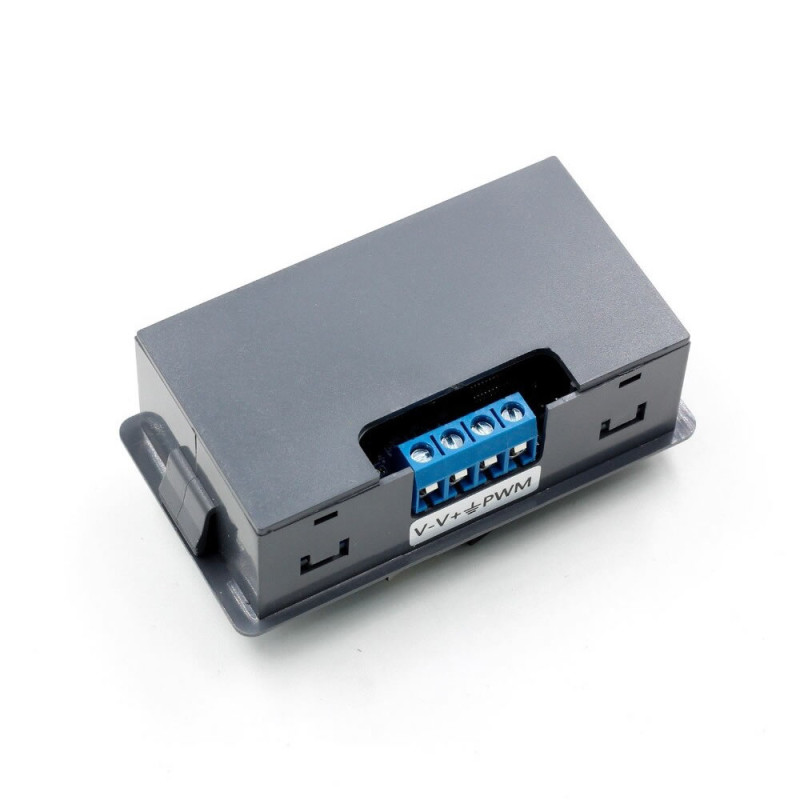
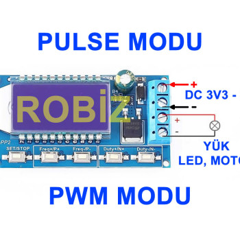
- Apply DC 3.3V - 30V to the supply input. Connect the PWM output to the signal (PWM) input of the board to be driven and connect the GND of both devices together.
- Turning the knob changes the selected value; a short press on the knob switches to the frequency setting. The upper line of the display shows the frequency, the lower line the duty cycle (%).
- After setting, lock the settings with a long press on the knob; since the knob is sensitive even a light touch can change the value, and the lock prevents this. Switching to precise mode is also done with a long press on the knob.
- The output amplitude is close to the supply voltage. If you drive a board with 3.3V or 5V input, supply the module with that voltage as well.
Application areas:
- Motor speed control (PWM input of a motor driver board)
- Fan speed setting
- LED brightness setting
- Dimmer and light control boards
- Servo motor testing
- Driver board and MOSFET board testing
- Trigger and timing signal
- Solenoid valve PWM control (with a driver board)
- Known signal source for frequency counter and oscilloscope trials
Things to consider:
- The output current is about 5mA - 30mA. Do not connect a motor, fan, LED strip, relay coil or solenoid directly to the output; use a motor driver, MOSFET or dimmer board in between.
- The output amplitude is close to the supply voltage. For example with a 12V supply the output is also about 12V; do not drive 3.3V or 5V input boards with this signal.
- The supply must not exceed 30V. Do not connect the supply wires in reverse.
- The frequency accuracy is about %2; it is not used as a reference source for work needing precise frequency such as instrument calibration.
Package contents:
- 1 pcs XY-PWM1 Signal Generator Module
- Note: Power adapter and connection cables are not included in the package.