- Stok Durumu: Stok Var
- Marka: OEM
- SKU: RBZ.100.368
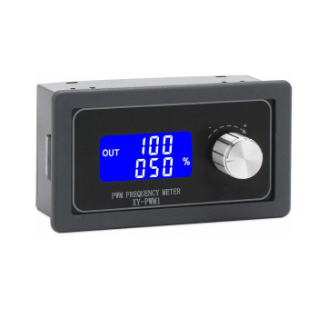
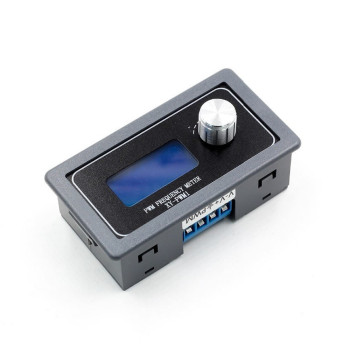
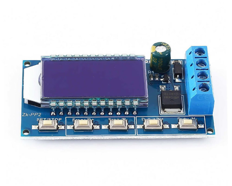
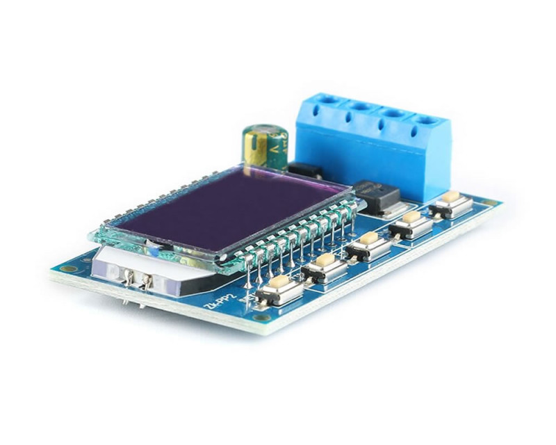
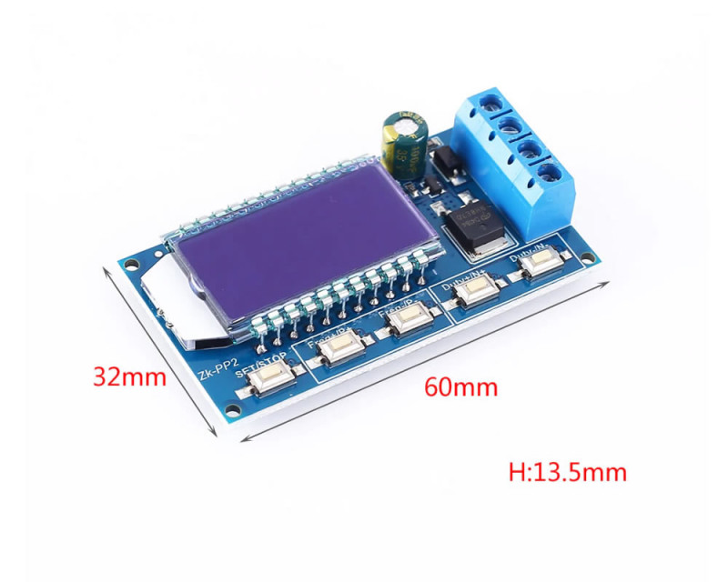
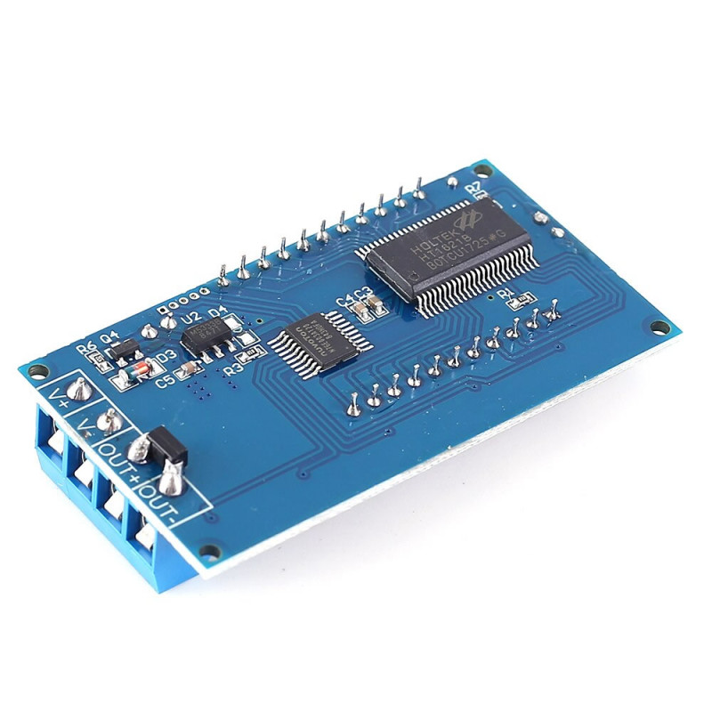
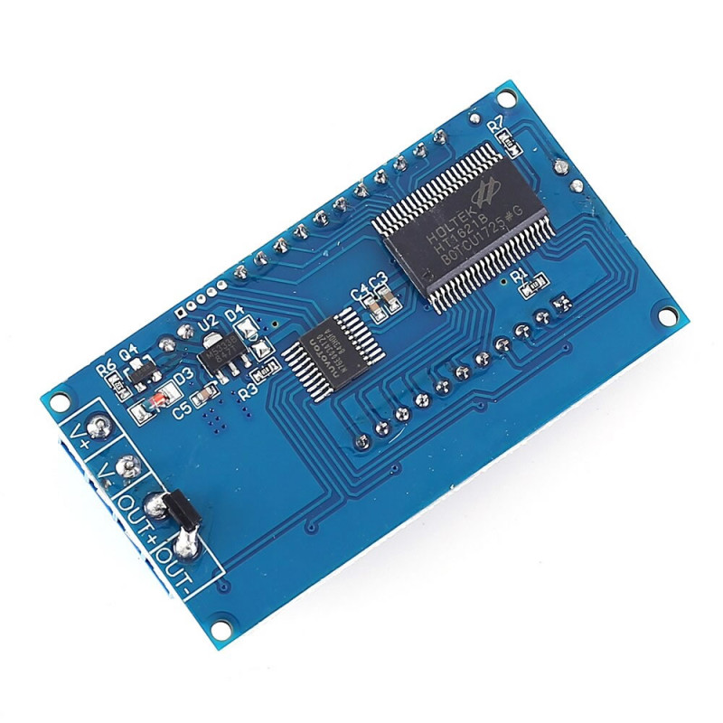
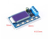
1Hz-150KHz Dual Mode ZK-PP2 PWM Signal Generator
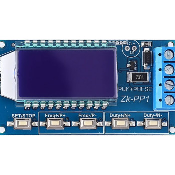
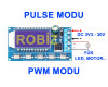
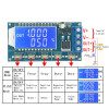
The ZK-PP2 signal generator produces electrical signals at various frequencies. It can generate square wave, pulse and output level signals. It has 2 operating modes. Pwm mode and pulse mode. It supports high current output and can be used to drive motors directly. It can be used as a signal source for various signal applications. It can be used in a wide variety of production and technological application areas.
Features:
- Dual mode: PWM mode and pulse mode
- High resolution lcd screen
- Frequency adjustment support
- Duty adjustment support
- High precision detection
- Ability to save settings to memory. Able to continue with these settings after a power outage
- 1 channel signal output
- Reverse voltage connection protection
- High current output power
- Ability to drive LED/Motor/solenoid valve directly.
Application areas:
- LED brightness adjustment. Frequency, duty cycle adjustable.
- Motor speed adjustment. Frequency, duty cycle adjustable.
- Drive solenoid valve on and off. Automatic cycle. Number of cycles (or infinite cycles) adjustable. Delay time adjustable.
- On/off function for various devices.
- Delayed start function. Delay time adjustable. Continuous or intermittent on/off operation function after a delay.
Parameters:
- Product name: ZK-PP2 PWM signal generator
- Model: ZK-PP2
- Operating voltage: DC 3.3V-30V
- Frequency range: 1Hz to 150KHz
- Motor speed control: 20KHz (typically)
- Frequency accuracy: 2%
- Duty cycle : 0.00%-100%
- Output Current: less than 8A (MOS switch) (We recommend not using above 5A.)
- Pulse count: 1 to 9999 or infinite
- Delay time: 0.000s to 9999s
- Pulse width: 0.000s to 9999s
- Time accuracy: 1ms
- Output amplitude: Same as input voltage
- Operating temperature: -40C to 85C
- Operating humidity: 0% to 95% RH
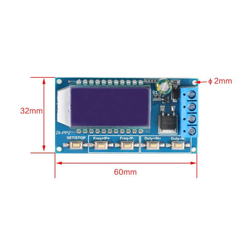
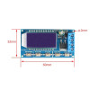
- Size: 60*32*13.5mm
Usage:
To briefly explain its usage; there are 2 operating modes. Pwm Mode and Pulse mode.
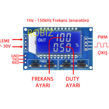
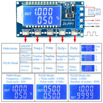
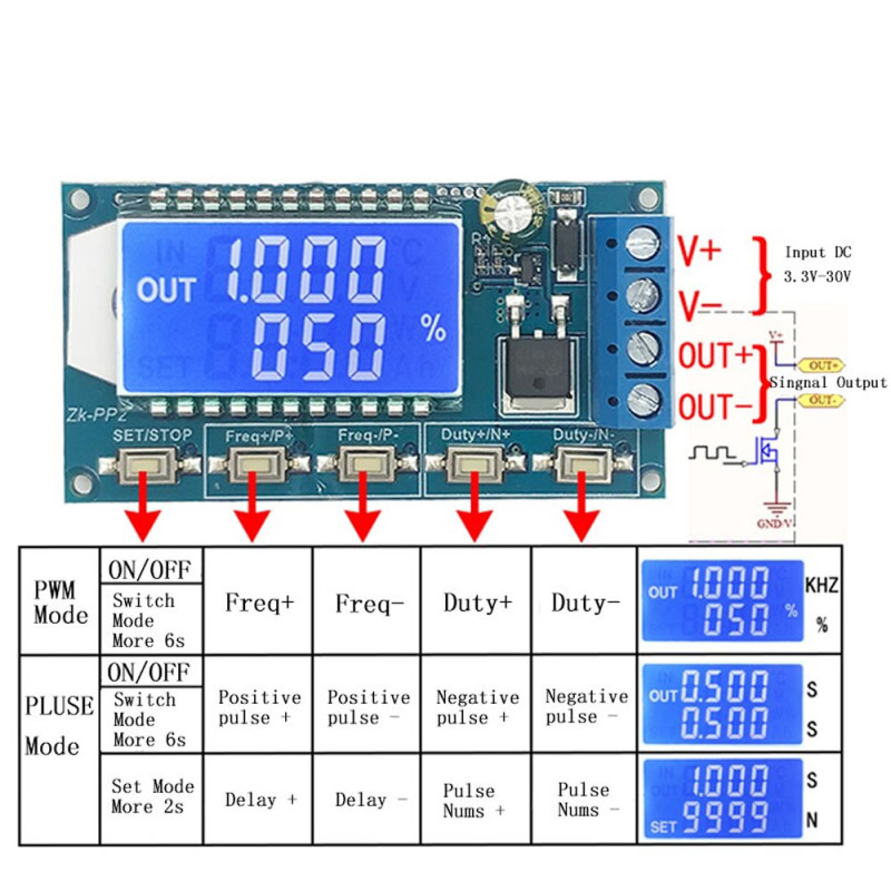
A short press on the Set button turns the output on and off. If the word Out appears on the left side, the signal is being transmitted to the output.
Pwm mode: Frequency and duty parameters can be adjusted. When the % sign is shown on the lcd, you can tell that it is in pwm mode. Frequency can be adjusted between 150khz and 0 hz. The output mosfet turns on and off at the speed set here. This process normally causes a square wave to form on the load. The duty (on/off setting) of this square wave can be adjusted..To give an example for duty; at 1 hz 50 duty, it stays on for 0.5 sec and stays off for 0.5 sec...
Pulse mode: If you press the set button for 6 seconds while in pwm mode, it switches to pulse mode. If the % symbol does not appear on the right side of the screen, the device is operating in pulse mode. The number at the top is the “on” time and the number at the bottom is the “off” time. It is used to turn the output on and off for certain periods. When set to 1-1; the device turns the output on for 1 second, keeps it off for 1 second. Basically both modes have the same effect on the load. But thanks to the additional delay and cycle settings in pulse mode, the device is turned into a kind of programmed signal generator.
If you hold the set button for 2 seconds while in pulse mode and release it, you enter the delayed start settings. Press the set button for another 2 sec to exit the delay settings. The number at the top is the delay time. The number at the bottom is the delay cycle count. If you leave it as ----, it will run with infinite cycles. If you set 2.5 at the top and 5 at the bottom; it will wait 2.5 sec and then run pulse mode. And it will apply the pulse mode settings 5 times.
The information below was generated using an automatic translation program. There may be translation errors.
1-PWM mode: frequency, duty cycle
- When '%' is displayed, it is in PWM mode.
- The factory default mode is PWM mode.
- The FREQ + and FREQ- buttons are used to set the output frequency. The user can press briefly to set the value in minimum units, or keep pressing continuously to adjust. The frequency range is from 1Hz to 150KHz.
- The duty + and duty- buttons are used to set the output duty cycle for the frequency. The user can press briefly to set the value in minimum units, or keep pressing continuously to adjust. The duty cycle range is from 0.00% to 100%.
- Press the 'stop' button briefly to enable or disable the output. When the screen symbol on the left shows 'OUT', the output is enabled. It is disabled when the screen symbol does not show 'OUT' and the module outputs 0V.
- The default factory frequency is 1 khz and the duty cycle is 50%.
- To change the operating mode: hold the 'SET' button for approximately 6 seconds. If the '%' symbol disappears on the right, it enters pulse mode.
2-Pulse mode: pulse width, delay, pulse number
- The screen symbol without '%' is PWM mode.
- The P+ and P- buttons are used to set the time for the positive pulse width. Displayed on the first line. Set time range 0.000s to 9999s.
- The N+ and N- buttons are used to set the time for the negative pulse width duration. Displayed on the second line. Set time range 0.000s to 9999s.
- Press the 'stop' button briefly to enable or disable the output. When the screen symbol on the left shows 'OUT', the output is enabled. It is disabled when the screen symbol does not show 'OUT' and the module outputs 0V.
- The default factory positive pulse width is 0.5 seconds and the negative pulse width is 0.5 seconds.
- To set the pulse count and delay time, press and hold the 'SET' button for 2 seconds. The screen will show the 'SET' symbol in the bottom left corner. Note: once in this mode, the output will be disabled and the output pulse will be cleared.
- The P+ and P- buttons are used to set the delay time. Set time range 0.000s to 9999s.
- Use the N+ and N- buttons to set the pulse count. Setting range is 1 to 9999 or infinite.
- The factory default delay time is 0 seconds and the pulse count is infinite (screen shows '----').
- Press the 'SET' button for 2 seconds to automatically return to the pulse interface.
- Press the 'stop' button briefly to delay the set time and start the pulse count.
- If the pulse count is sent, it will automatically output 0V. If the 'stop' button is pressed during output, the output will be disabled and the pulse numbers will be cleared.
- Each time the module is powered on, the set number of pulses is output.
Practical application:
- PWM output 20KHz,60%: select PWM mode. Set the frequency to 20.00 and the duty cycle to 060%.
- Output on for 0.6s, off for 0.2s, turn on infinite cycle: select pulse mode. Set the positive pulse width to 0.600 and the negative pulse width to 0.200. Delay time 0.000. Set pulse count to '----'.
- After power on, wait 5s delay or press the 'STOP' button. Then turn on output 0.6s, off 0.2s, infinite cycle: select pulse mode. Set the positive pulse width to 0.600 and the negative pulse width to 0.200. Delay time 5.000. Set pulse count to '----'.
- After power on, wait 5s delay or press the 'STOP' button. Then output a 10ms high level signal, 10ms low level signal, cycle 100 times: select pulse mode. Set the positive pulse width to 0.010 and the negative pulse width to 0.010. Delay time 5.000. Pulse count 0100.
- After power on, 5s delay. Then hold the output: select pulse mode. Set positive pulse width to any value greater than 0 (any value) and negative pulse width to 0.000. Delay time 10.00. Set pulse count to '----'.
Usage Steps:
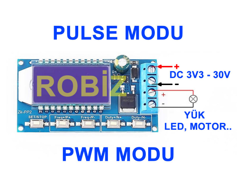
- Connect to the power supply.
- Select the operating mode.
- Adjust the frequency parameter with a short or long press of 'FREQ+' or 'FREQ-'.
- Press briefly or hold the 'duty+' or 'duty-' button to adjust the parameter.
- Connect to the load.
Application:
- Applications for generating square wave signals for use on experiment boards.
- Used to generate square wave signals for motor driver control applications
- Generation of adjustable pulses for use by an Mcu
- Dimmer applications
- On speed regulator application boards.
Note:
- It has 1 channel signal output.
- The maximum output current is 8A. Therefore it can directly drive high power devices such as motors. (We recommend not using above 5A.)
- Read the user manual and its description before use.
Package Contents:
- 1 pcs ZK-PP2 PWM Signal Generator