- Stok Durumu: Stok Var
- Marka: OEM
- SKU: RBZ.101.611
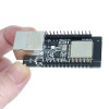
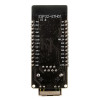
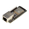
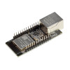
ESP32-ETH01 Ethernet to Wifi / Bluetooth Converter Gateway Module
Embedded Serial Port Wireless Communication Board WT32-ETH01
Pin headers are unsoldered on the boards in stock.
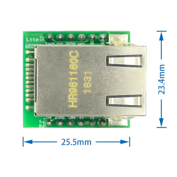
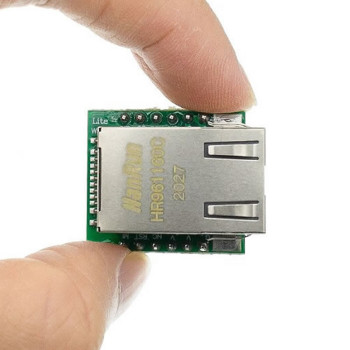
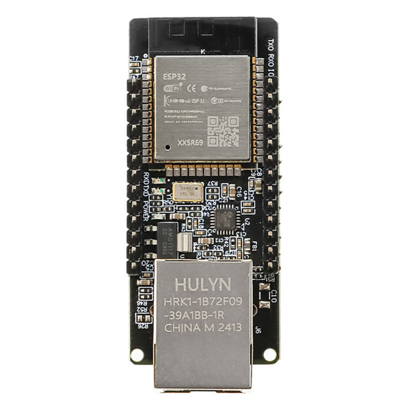
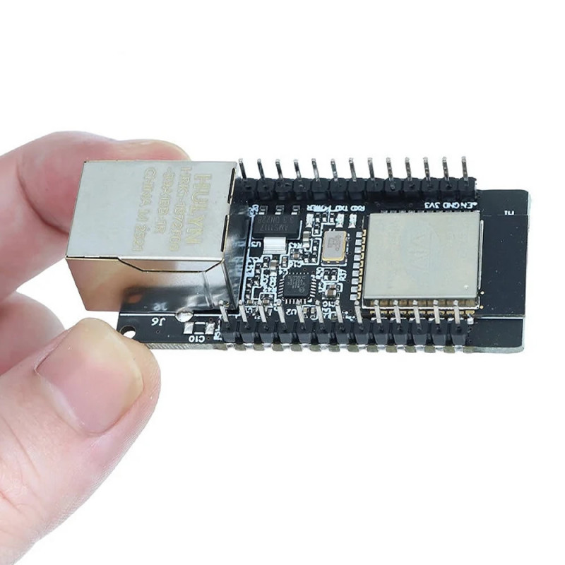
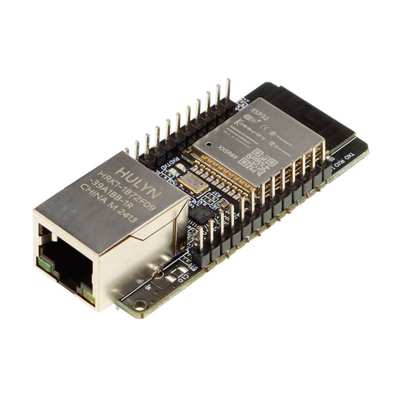
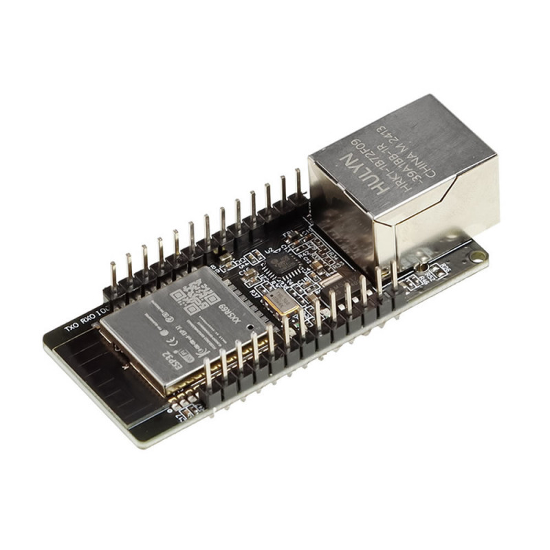
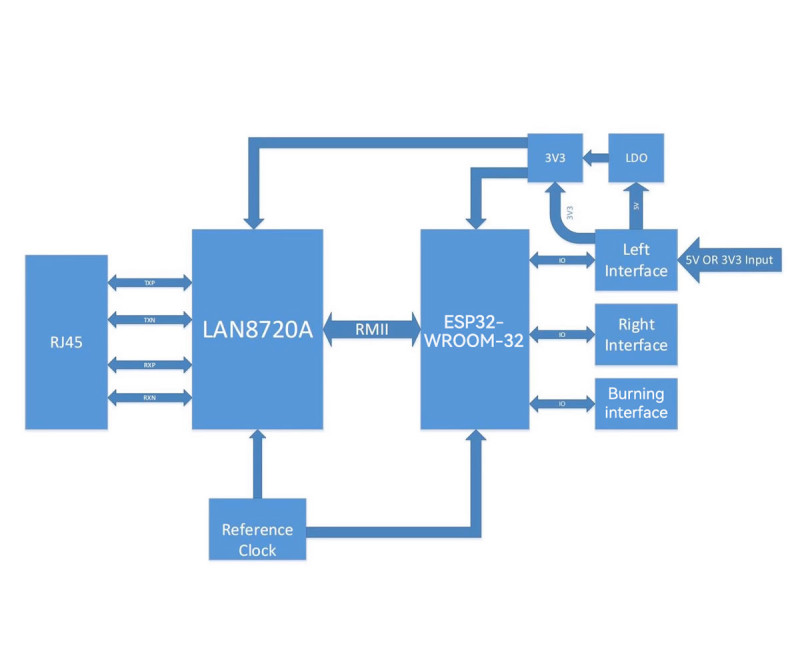
ESP32-ETH01 is a network module that combines the dual-core ESP32 processor, the LAN8720A Ethernet physical layer chip and an RJ45 Ethernet socket on a single board (same structure and pinout as WT32-ETH01). It connects to a wired network with 10/100Mbps Ethernet and to a wireless network with 2.4GHz WiFi; it also supports Bluetooth 4.2 (classic and BLE). It has 4MB flash memory, is powered from 5V or 3.3V and draws 80mA on average.
The board comes with the manufacturer firmware as a serial port to Ethernet converter (transparent transmission): data entering through UART2 (IO5 RXD2, IO17 TXD2) is passed to the network over TCP or UDP; IP, subnet mask and gateway are set with AT+ commands, static IP or DHCP can be used, and the default serial setting is 115200 baud, 8N1. If desired, the board can be reprogrammed with your own program; in that case Ethernet, WiFi and Bluetooth are used from the same ESP32.
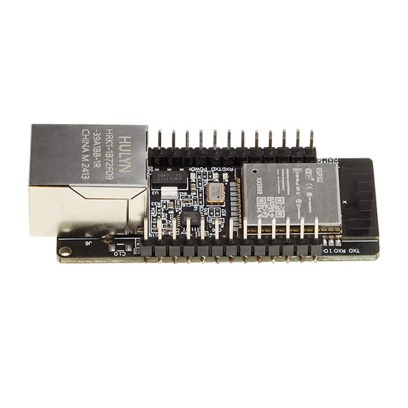
Both long edges of the board have 2.54mm pitch pins and half holes (castellated pads): headers can be soldered for use with cables or a breadboard, or the module can be soldered directly onto your own board. The separate 6-pin connection on the top edge (EN, GND, 3V3, TXD0, RXD0, IO0) is for programming; there is no USB converter on the board.
Key features:
Ethernet + WiFi + Bluetooth on one board: 10/100Mbps wired network with LAN8720A, 2.4GHz WiFi and Bluetooth 4.2 with ESP32; no separate Ethernet module or wiring needed.
Ready serial port to Ethernet converter: The manufacturer firmware passes serial data to the network in TCP Server / Client and UDP Server / Client modes; settings are made with AT+ commands.
Ready pin for RS485: The 485_EN (IO33) pin is for direction control of an RS485 transceiver; Modbus RTU devices can be connected to the network over the serial line. The RS485 transceiver (e.g. MAX485) is not on the board and must be added separately.
Two mounting types: Cable or breadboard connection with through-hole 2.54mm pins, direct soldering onto a board with half-hole edge pads.
Status indicators: Power LED, RXD / TXD LEDs that light with data flow on the serial line, and green link and yellow data LEDs on the RJ45.
Features:
- Product type: ESP32 based Ethernet + WiFi + Bluetooth module, serial port to Ethernet converter
- Model: ESP32-ETH01 (WT32-ETH01 compatible)
- Processor: ESP32, dual core, up to 240MHz, 520KB SRAM
- Flash memory: 4MB (32Mbit)
- Ethernet: LAN8720A, RJ45, 10/100Mbps, automatic crossover / straight cable detection
- WiFi: 802.11 b/g/n/e/i, 2.4GHz - 2.5GHz, up to 150Mbps on 802.11n
- WiFi modes: Station, SoftAP, SoftAP + Station, P2P
- Bluetooth: v4.2 BR/EDR and BLE
- Serial port speed: 80 - 5000000 baud (default 115200, 8N1)
- Network protocols: IPv4, TCP / UDP; TCP Server, TCP Client, UDP Server, UDP Client; static IP or DHCP
- Ready firmware: transparent transmission, AT+ command set, remote (OTA) firmware update over the network
- Security: WPA / WPA2 / WPA2-Enterprise / WPS; AES / RSA / ECC / SHA encryption
- Supply: 5V or 3.3V (only one of the two)
- Current: 80mA on average; the power source must supply at least 500mA
- User pins: IO2, IO4, IO12, IO14, IO15; input only IO35, IO36, IO39; RXD2 (IO5), TXD2 (IO17), CFG (IO32), 485_EN (IO33), LINK
- Programming: 6-pin connection (EN, GND, 3V3, TXD0, RXD0, IO0); no USB on the board
- Indicators: power LED, RXD / TXD LEDs, green link and yellow data LEDs on the RJ45
- Antenna: on-board PCB antenna
- Mounting: 2.54mm through-hole pins and half-hole edge pads, 2 mounting holes
- Operating temperature: -40°C - 85°C
- Color: Black
- Dimensions: about 58mm x 26mm, height with RJ45 socket about 17mm
- Weight: about 15gr
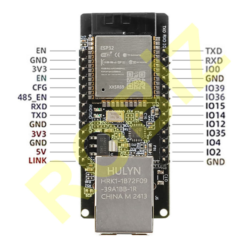
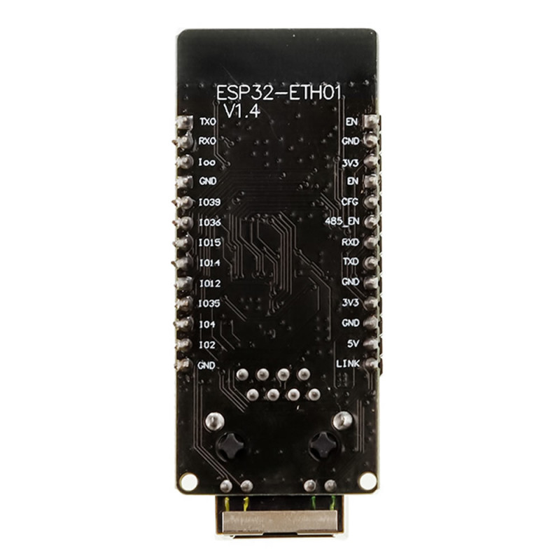
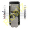
Pin descriptions:
- 1 EN: Enable, active high (enabled by default)
- 2 CFG: IO32, configuration pin
- 3 485_EN: IO33, RS485 direction control output
- 4 RXD: IO5, RXD2
- 5 TXD: IO17, TXD2
- 6 GND
- 7 3V3: 3.3V supply input
- 8 GND
- 9 5V: 5V supply input
- 10 LINK: Network connection indicator pin
- 11 GND
- 12 IO39: input only
- 13 IO36: input only
- 14 IO15
- 15 IO14
- 16 IO12
- 17 IO35: input only
- 18 IO4
- 19 IO2
- 20 GND
Usage information:
- Use only one supply: apply 5V to the 5V pin or 3.3V to the 3V3 pin. When the power LED lights, the board is running. The source must be able to supply at least 500mA.
- When using the ready serial port to Ethernet firmware, connect the TX line of your device to RXD (IO5) and the RX line to TXD (IO17); the serial line is 3.3V logic. Make the network settings (IP, gateway, TCP / UDP mode) with AT+ commands.
- To upload your own program, connect a 3.3V logic USB-TTL converter crosswise to the 6-pin programming connection (converter TX to RXD0, RX to TXD0); restart the board while keeping IO0 connected to GND, and remove the IO0 connection when the upload is finished.
- Ethernet setting in your own software: PHY LAN8720, PHY address 1, MDC IO23, MDIO IO18, PHY power pin IO16, clock IO0 input.
Applications:
- Gateway connecting serial port (RS232 / RS485) devices to an Ethernet or WiFi network (with a level shifter for RS232, a transceiver for RS485)
- PLC and field device communication with Modbus TCP
- Reading energy meter and analyzer data over the network
- Remote monitoring and data acquisition with MQTT
- Wired home automation nodes (Tasmota, ESPHome)
- Greenhouse, agriculture and warehouse environment monitoring stations
- Web server and control panel running on a wired network
- Wired sensor node where the WiFi signal is weak
- Connecting door access, turnstile and counter devices to the network
- Network devices configurable over Bluetooth
Things to consider:
- Do not apply 3.3V and 5V supply at the same time. Do not apply more than 5V to the 5V pin; the AMS1117 regulator on the board heats up and the board can be damaged.
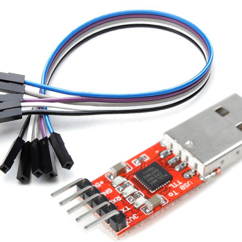
- There is no USB socket or USB-TTL converter on the board; a separate 3.3V logic USB-TTL converter is needed for programming. Do not connect a 5V logic serial line.
- IO35, IO36 and IO39 are input only and cannot be used as outputs. IO0 is used as the Ethernet clock input; IO16, IO18, IO23 and the RMII bus pins are reserved for Ethernet, do not use them for other purposes.
- The WiFi antenna is on the board, there is no external antenna socket; inside a metal box the WiFi and Bluetooth range drops.
- Pin headers are unsoldered on the boards in stock; before use, headers must be soldered or the board must be soldered onto your own board through the half-hole pads.
Software support:
- github.com/egnor/wt32-eth01
- github.com/SIMS-IOT-Devices/FreeRTOS-ESP-IDF-5.0-WT32-ETH01/blob/main/Blink_WT32-ETH01.c
Package contents:
- 1 Piece ESP32-ETH01 Ethernet WiFi Bluetooth Module
- Note: USB-TTL converter, Ethernet cable and power supply are not included in the package.