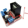
- Stok Durumu: Stok Var
- Marka: OEM
- SKU: RBZ.100.876
L298N Dual DC Motor Driver Module
PWM Speed Direction Control 25W 78M05 Regulator 12V 24V Gear Motor Bipolar Smart Car Robot Tank Conveyor Pump Curtain Door
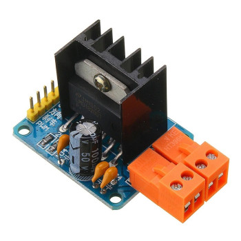
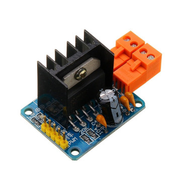
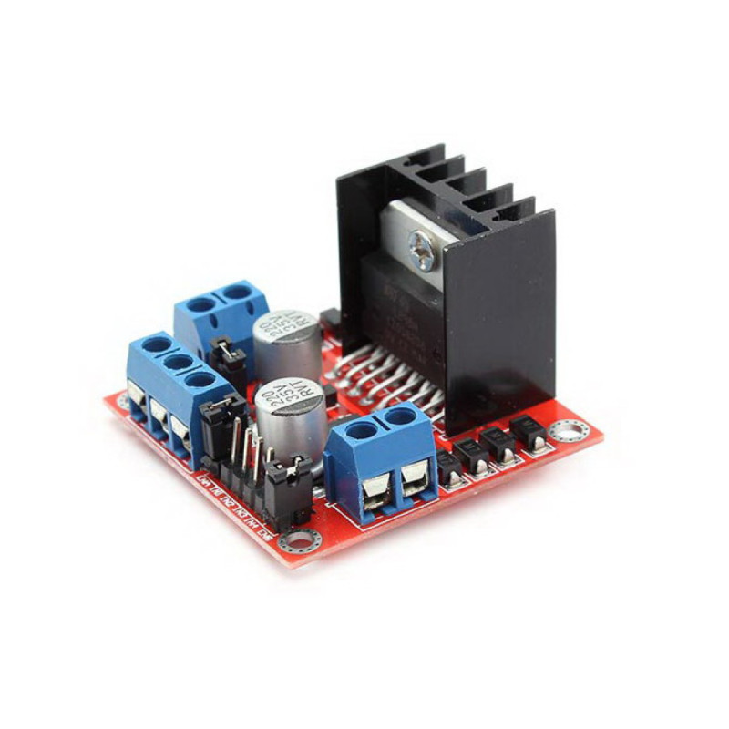
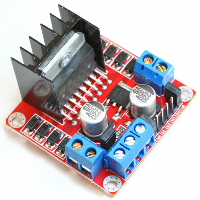
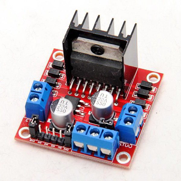
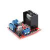
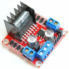
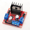
The L298N Module is a motor driver board with heatsink built with the L298N dual H bridge IC. With a 5V-35V motor supply it drives two DC motors separately forward, reverse and with PWM speed control, or runs one 2 phase (bipolar) stepper motor. It delivers up to 2A per channel; the IC is screwed to a black heatsink and the total power is up to 25W. Motors connect to the blue screw terminals and the supply to the 3-way terminal; no soldering is needed.
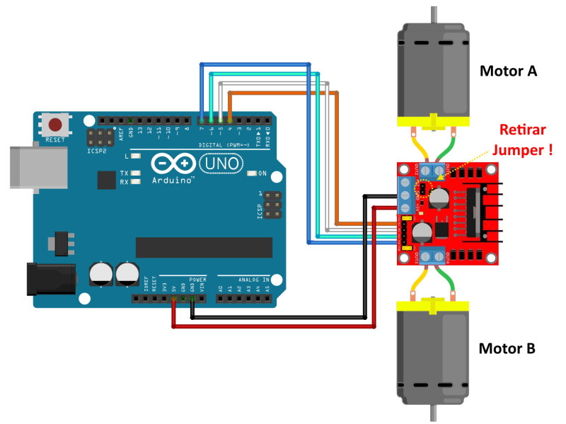
The 78M05 regulator on the board produces 5V for the logic part of the board from the motor supply while the 5V jumper is fitted, and this 5V can also be taken out from the terminal; when the motor supply exceeds 12V the jumper is removed and 5V is supplied externally. The control inputs (ENA, IN1, IN2, IN3, IN4, ENB) accept anything above 2.3V as high, so they can be driven directly by 5V and 3.3V microcontrollers. With the jumpers on ENA and ENB fitted the motors run at full speed; when the jumper is removed and PWM is applied to these pins the speed is adjusted.
Key features:
Wide 5V-35V supply: The same board is used from 6V gear motors up to 12V and 24V motors; it works at voltages where small battery drivers are not enough.
2A output with heatsink: Up to 2A per channel, up to 25W in total; the heatsink screwed to the IC spreads the heat during long operation.
On-board 5V regulator: With the jumper fitted the 78M05 regulator powers the board from the motor supply and gives a 5V output; no separate 5V adapter is needed.
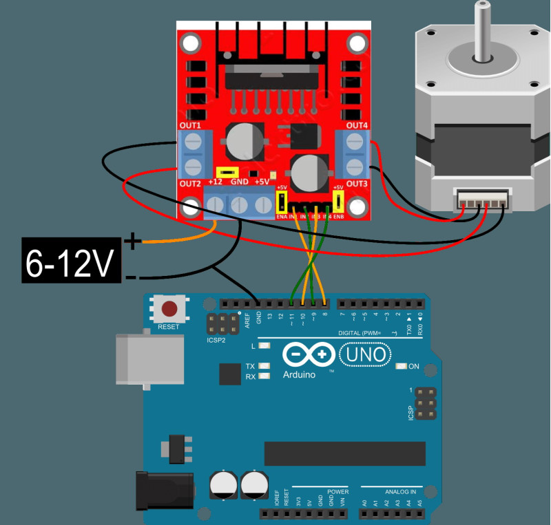
Two motors or one stepper: Drives two DC motors with independent direction and speed control, or one bipolar stepper motor with the four input pins.
Screw terminal connection: Motor outputs and supply are on screw terminals, control pins on a 2.54mm pin header; it is fixed to a chassis with 4 mounting holes.
Features:
- Driver IC: L298N dual H bridge DC motor driver IC
- Motor supply voltage (Vs): 5V - 35V (at least 7V when the on-board regulator is used)
- Output current: continuous up to 2A per channel; repetitive peak 2.5A, instantaneous (100µs) peak 3A (L298 datasheet)
- Total power: up to 25W
- Motors driven: 2 DC motors (direction and speed) or 1 two phase (bipolar) stepper motor
- Logic supply (Vss): 5V; logic current 0 - 36mA
- Control inputs (IN1 - IN4): Low -0.3V - 1.5V, High 2.3V - Vss; can be driven with 3.3V and 5V signals
- Enable inputs (ENA, ENB): with jumpers; PWM speed control when the jumper is removed (Low -0.3V - 1.5V motor stops, High 2.3V - Vss motor runs)
- Regulator: 78M05, gives 5V output while the 5V jumper is fitted (motor supply up to 12V)
- Output voltage drop: according to the L298N datasheet up to approx. 3.2V at 1A, up to approx. 4.9V at 2A
- Protection: back EMF diodes on the motor outputs
- Indicators: power LED
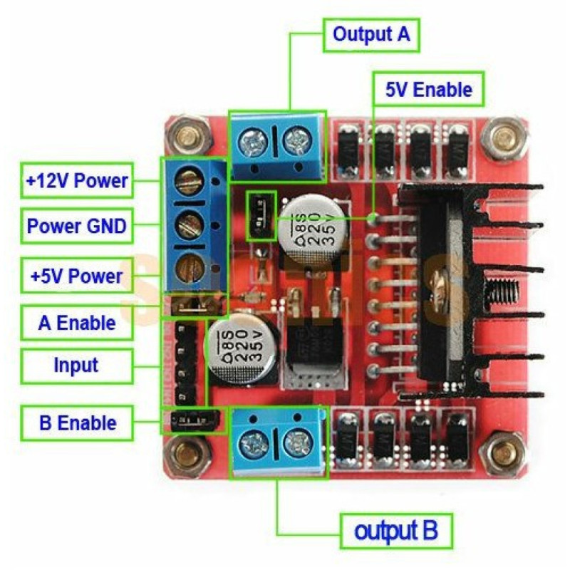
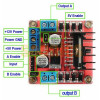
- Connections: OUT1 - OUT2 (Motor A) and OUT3 - OUT4 (Motor B) 2-way screw terminals; 12V, GND, 5V 3-way screw terminal; ENA, IN1, IN2, IN3, IN4, ENB pin header
- Mounting: 4 mounting holes
- IC junction operating temperature: -25°C to +130°C (L298 datasheet; not the ambient temperature)
- Heatsink: black, screwed to the IC
- Color: Red PCB, blue terminals
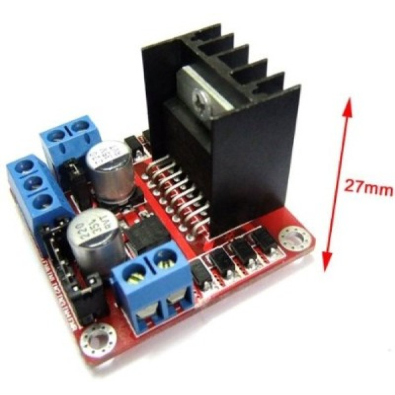
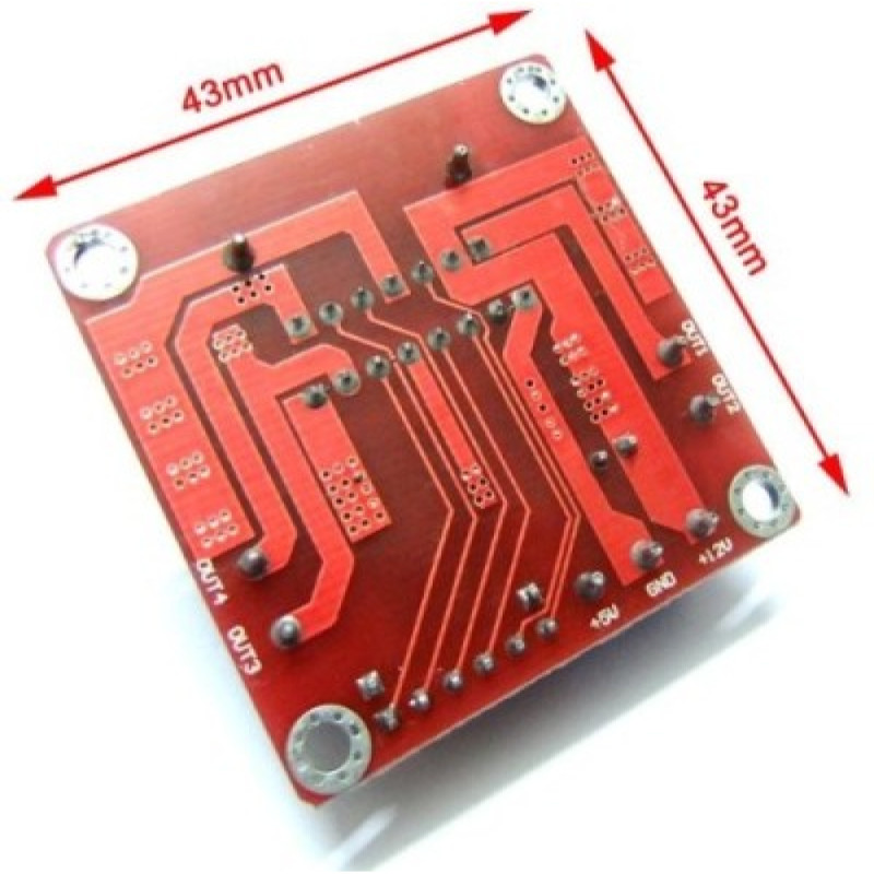
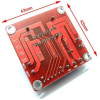
- Dimensions: approx. 43mm x 43mm x 27mm (including heatsink)
- Weight: approx. 30gr
Usage information:
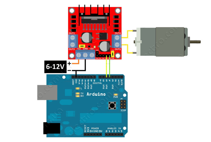
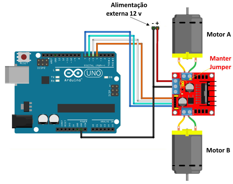
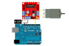
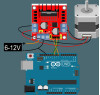
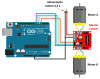
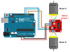
- Supply: Connect the motor supply (+) to the 12V terminal and (-) to the GND terminal. If the supply is between 7V and 12V the 5V jumper stays fitted and 5V for the microcontroller can be taken from the 5V terminal. If the supply exceeds 12V remove the 5V jumper and connect a separate 5V source to the 5V terminal.
- Direction: With IN1 high and IN2 low Motor A turns one way; with IN1 low and IN2 high it turns the other way. If IN1 and IN2 are at the same level the motor stops. IN3 and IN4 are used the same way for Motor B.
- Speed: Remove the ENA and ENB jumpers and connect the PWM output of the microcontroller to these pins; the motor speeds up as the duty cycle increases. Always connect the GND of the board to the GND of the microcontroller.
Application areas:
- Two-motor smart car and line follower vehicle
- Tracked robot tank and mobile robot platform
- Conveyor belt with 12V gear motor
- DC pump and fan speed control
- Motorized curtain and shutter
- Motorized door, slider and lock mechanism
- Slider, turntable and positioning with bipolar stepper motor
- Solar panel tracking system
- Motor control experiments at school and in the workshop
Things to consider:
- If the motor supply exceeds 12V always remove the 5V jumper; with the jumper fitted the high voltage heats the 78M05 regulator and can damage it.
- The L298N is an older transistor type driver; the voltage reaching the motor stays a few volts below the supply voltage (up to approx. 3.2V at 1A). If the motor lacks power, increase the supply voltage as far as the motor allows.
- With motors drawing more than 2A per channel or high current at start-up the board heats up; choose a higher current MOSFET driver for such motors. Although the board accepts up to 35V supply, 24V and below is recommended for long life.
- If the board and microcontroller GNDs are not connected the control signals do not work. Check the polarity before connecting the supply.
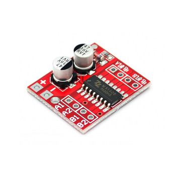
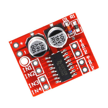
- This is the large, approx. 43mm x 43mm L298N board with heatsink; the small MX1508 board with L298N in its name, for small battery toy motors, is a separate product.
Package contents:
- 1 x L298N Motor Driver Module
- 1 x Heatsink ( Assembled )
- Note: Motor, power adapter and connection cables are not included in the package.