- Stok Durumu: Stok Var
- Marka: OEM
- SKU: RBZ.100.907
SOIC8 SOP8 to DIP8 Test Clip
Eprom Flash Bios Programming Clip SPI IIC
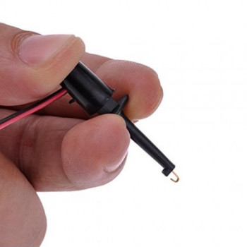
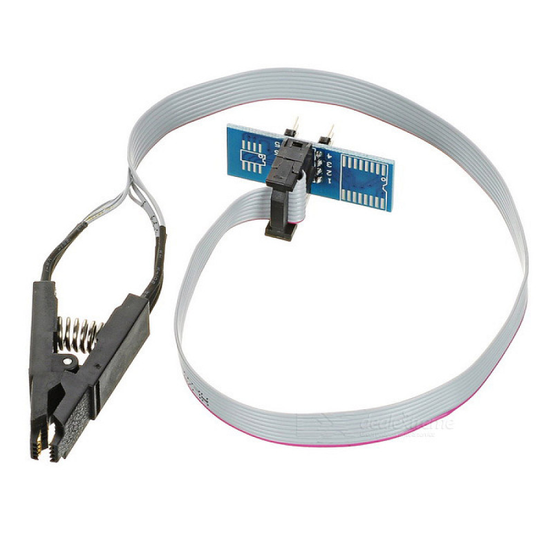
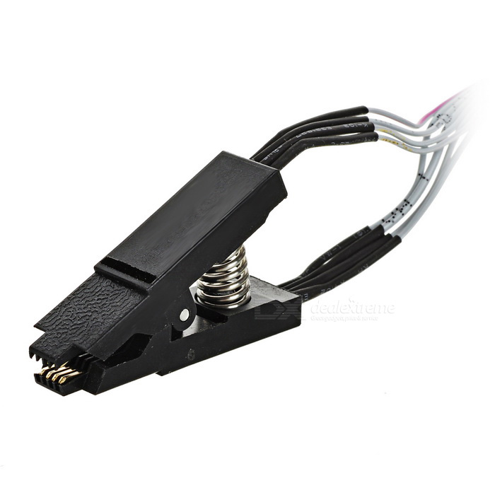
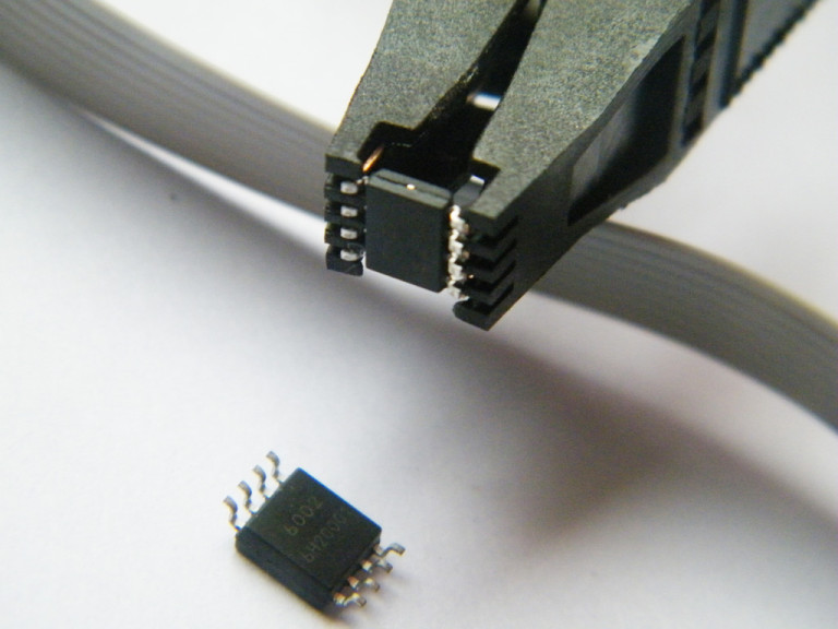
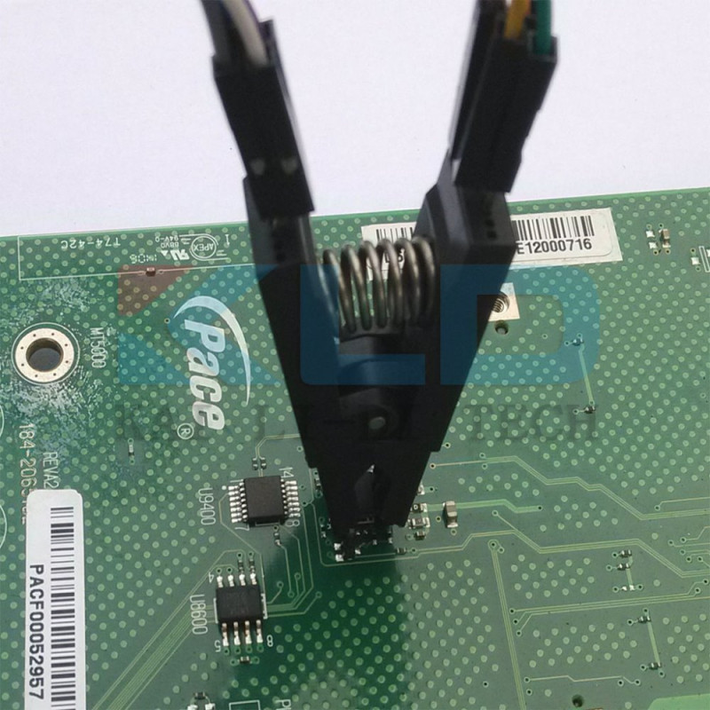
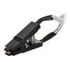
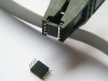
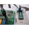
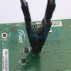
The SOIC8 Test Clip is a spring-loaded programming clamp used to read, write and back up 8-lead SOIC8 / SOP8 EEPROM and flash ICs soldered on a board, without removing them from the circuit. It can be used on ICs with 1.27mm (50mil) lead pitch in both narrow (150mil) and wide (200mil) bodies. 24Cxx, 25xx and 93Cxx series ICs and motherboard and laptop BIOS ICs can be read with this clip.
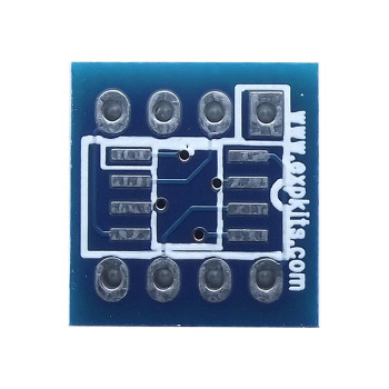
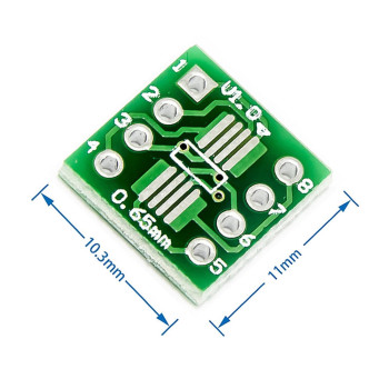
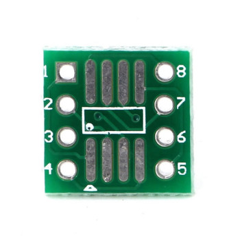
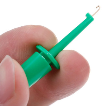
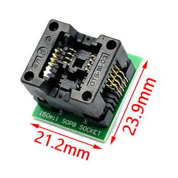
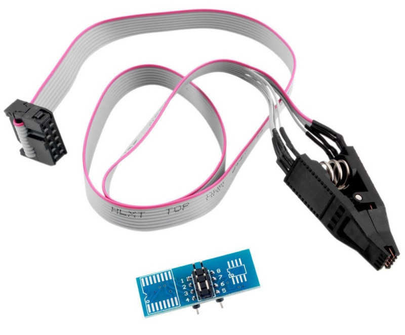
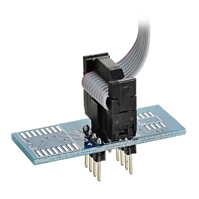
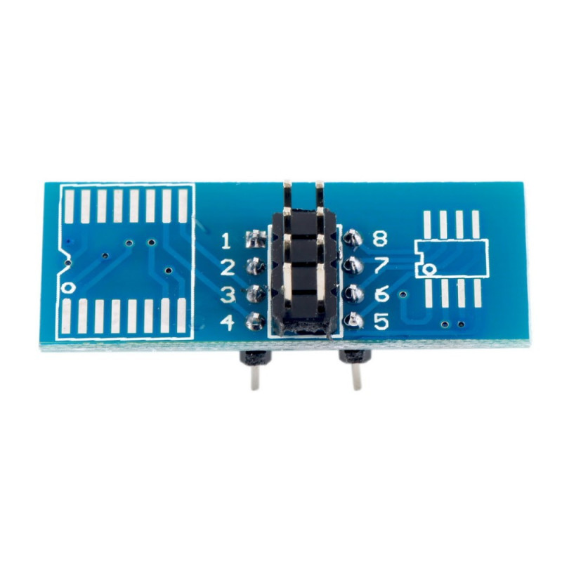
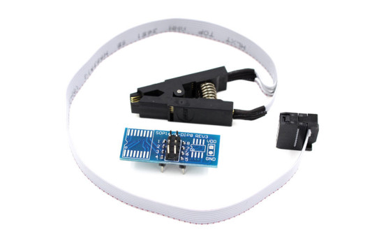
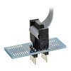
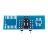
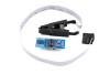
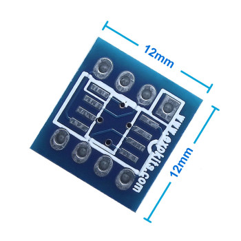
Thanks to the spring in its ABS plastic body, the clamp grips the leads on both sides of the IC from above and stays in place without being held by hand. The end of the 35cm, 8-wire grey flat cable attached to the clip plugs into the adapter board in the package; the DIP8 pins on the bottom of the adapter board fit into the DIP8 socket of the programmer. The red striped wire of the cable shows the pin 1 side. The adapter board also has SOP8 IC soldering pads; a removed IC can also be programmed by soldering it onto these pads.
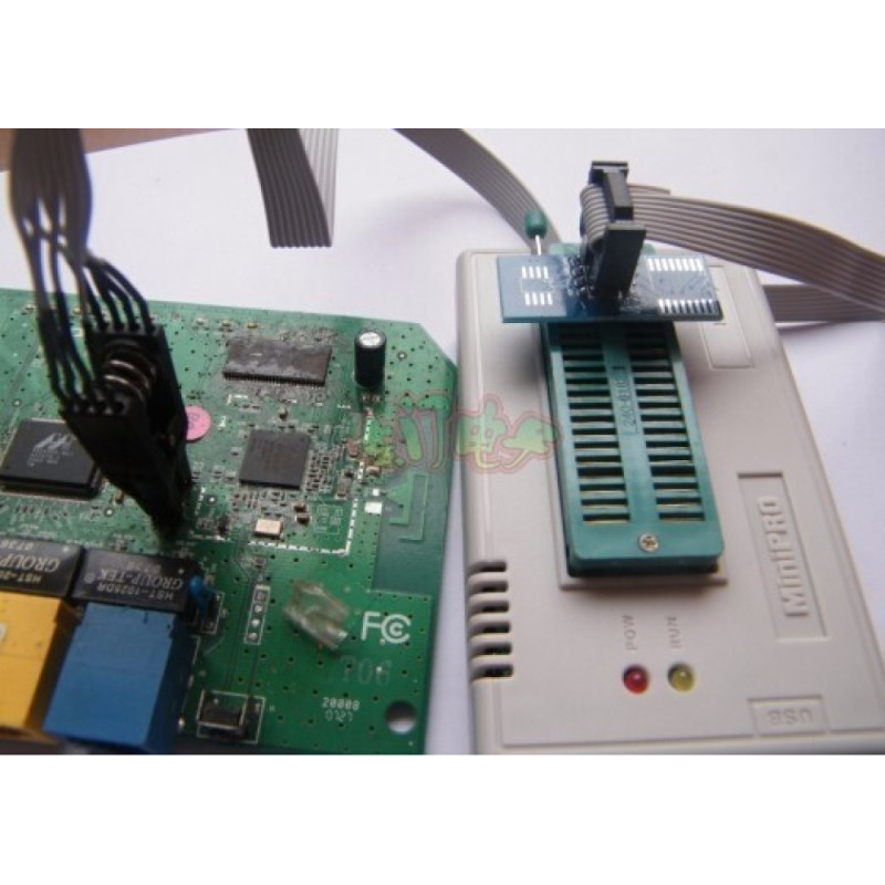
It is widely used in electronics service work for computer and laptop BIOS repair and for backing up and restoring SPI flash firmware on modem, router, television and monitor main boards. The clamp, the attached cable and the adapter board come together in the package; it can be used immediately with a programmer that has a DIP8 socket.
Key features:
Programming without removal: The spring clamp grips the IC while it is on the board; there is no need to desolder and resolder the IC, and no heat damage is done to the board or the IC.
Narrow and wide body support: The same clip is used on narrow (150mil) and wide (200mil) body SOIC8 / SOP8 ICs with 1.27mm lead pitch.
Ready cable and adapter: The 35cm flat cable attached to the clip and the DIP8 adapter board are in the package; it connects to the DIP8 socket of the programmer without making extra cables.
Common IC families: Used with 24Cxx (I2C), 25xx (SPI flash and EEPROM) and 93Cxx (Microwire) series 8-lead EEPROM and flash ICs.
Easy orientation: The red striped wire of the cable shows the pin 1 side, and the pin number prints on the adapter board show the connection direction.
Features:
- Product type: SOIC8 / SOP8 IC test clip (programming clamp), with cable
- Supported packages: SOIC8, SOP8 (8 leads)
- IC lead pitch: 1.27mm (50mil)
- Supported body types: Narrow (150mil) and wide (200mil) body ICs
- Supported ICs: 24Cxx (I2C), 25xx (SPI flash and EEPROM), 93Cxx (Microwire) series EEPROM and flash ICs
- Connection method: Spring clamp grips the IC leads from above while on the board
- Adapter board: 2 x 4 pin header for the cable connector, DIP8 output pins on the bottom
- Adapter board extra use: SOP8 IC soldering pads (for a removed IC)
- Connection structure: Passive, clamp pins are connected through the adapter board to the DIP8 pins with the same numbers; no power or software required
- Pin 1 mark: Red striped wire of the cable, pin number prints on the adapter board
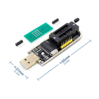
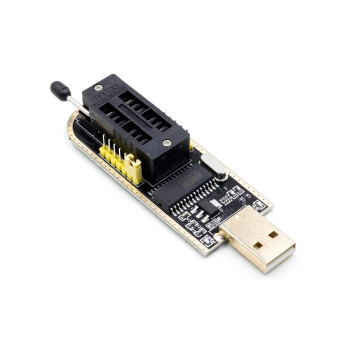
- Compatible programmers: Programmers with a DIP8 socket that can read in-circuit (e.g. CH341A, TL866II Plus, T48, RT809H)
- Usage: In-circuit reading, writing and backup without desoldering
- Cable: 8-wire grey flat cable, attached to the clip
- Material: ABS plastic clip body, PCB adapter board
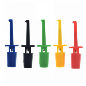
- Colour: Black clip, grey cable, blue adapter board
- Cable length: 35cm
- Dimensions (including cable): approximately 40cm x 4cm x 2cm
- Weight: 18gr
Usage information:
- Insert the adapter board into the DIP8 socket of the programmer so that the pin 1 mark on the board faces the pin 1 side of the programmer; plug the cable connector into the 2 x 4 pin header on the adapter board.
- Switch off the device. Find pin 1 of the IC, marked by a dot or notch, and seat the clip on the IC so that the red striped wire of the cable comes to this pin; check that all 8 tips of the clamp press fully on the leads.
- Select the IC model in the programmer software, do an ID read first, then read the content of the IC and save a backup; write only after the backup is taken.
Areas of use:
- Desktop computer motherboard BIOS repair and update
- Laptop BIOS backup and repair
- Modem and router SPI flash firmware backup
- Television and monitor main board firmware loading
- Printer main board EEPROM and flash work
- Reading 93Cxx / 24Cxx EEPROMs in car instrument clusters and electronic units
- Copying EEPROM and flash content in electronics service
- Checking SPI flash and EEPROM content in your own circuits
- Electronics training and laboratory work
Precautions:
- Switch off the device before attaching the clip; on a laptop the battery and the CMOS battery must be removed. While powering the IC, the programmer may also power other parts of the board; if reading fails, the IC may need to be removed and programmed on the adapter board.
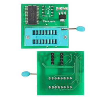
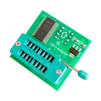
- Check the operating voltage of the IC (1.8V, 3.3V or 5V). The output voltage of the programmer must suit the IC; on programmers without 1.8V support (e.g. CH341A) a separate 1.8V converter adapter is needed for 1.8V ICs.
- If the clip is attached in reverse, the IC and the programmer may be damaged. The red striped wire of the cable must always come to pin 1 of the IC.
- Always read and back up the original content of the IC before writing; a wrongly written BIOS or firmware can make the device inoperable.
Package contents:
- 1 Piece SOIC8 Test Clip
- 1 Piece 35cm flat cable ( Assembled )
- 1 Piece DIP8 adapter board
- Note: Programmer is not included in the package.