- Stok Durumu: Stok Var
- Marka: TOSHIBA
- SKU: RBZ.100.843
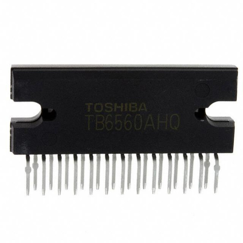
TB6560AHQ Stepper Motor Driver IC Toshiba 3.5A Peak 34V HZIP25 1/16 Microstep
Bipolar 2 Phase PWM Current Adjustable CNC Router Milling Laser Cutting Engraving 3D Printer Plotter Camera Slider Telescope Conveyor
The TB6560AHQ is a PWM chopper-type stepper motor driver IC made by Toshiba for driving two-phase bipolar stepper motors, combining the control circuit and the power stage in a single package. The motor supply is 4.5V - 34V and the logic supply is 5V; it delivers 3A operating current and 3.5A peak current per phase. Using only a clock (CLK) and a direction (CW/CCW) signal it turns the motor forward and backward, and with sinusoidal current steps it runs with low vibration at up to 1/16 microstep.
The IC comes in a 25-pin HZIP25 package; its back side and the two screw slots on the sides allow direct mounting on a heatsink. Step mode is selected with the M1/M2 pins, current ratio with TQ1/TQ2 and current decay mode with DCY1/DCY2; the motor current is set by external current sense resistors. Thermal shutdown, RESET and ENABLE inputs and the Protect and MO monitor outputs are built into the IC.
This product is a single IC; it is not a ready driver board or a boxed driver. It suits those designing their own stepper driver board, makers of CNC and 3D printer controller boards, and anyone replacing a burnt IC on common TB6560 driver boards.
Key features:
Control and power stage in one chip: The step sequencer, PWM current control and two full H-bridge outputs are in the same IC. Only current sense resistors, an OSC capacitor and a few passive parts are needed externally.
Microstepping up to 1/16: 2-phase (full step), 1-2-phase (half step), 2W1-2-phase (1/8) and 4W1-2-phase (1/16) excitation modes are selected with the M1/M2 pins; at higher microstep the motor turns quieter and smoother.
Adjustable motor current: The current is set by the sense resistor using IOUT = 0.5V / RNF (1A with 0.5Ω). The TQ1/TQ2 pins select 100%, 75%, 50% or 20% of this current; the 20% setting reduces heating while the motor is holding.
High voltage and current: Works with a 4.5V - 34V motor supply (absolute maximum 40V) and delivers 3A operating and 3.5A peak current per phase. Output on-resistance (upper + lower) is 0.6Ω typical.
Protection and monitoring: Thermal shutdown at about 170°C switches the outputs off and pulls the Protect pin low. The MO pin reports the initial position; when ENABLE is low the outputs are off.
Features:
- Product type: PWM chopper-type bipolar stepper motor driver IC (single chip, control and power stage)
- Model: TB6560AHQ (Toshiba)
- Motor supply voltage (VMA/VMB): 4.5V - 34V operating range, absolute maximum 40V
- Logic supply voltage (VDD): 4.5V - 5.5V (typical 5V)
- Output current: 3A operating, 3.5A peak per phase (absolute maximum)
- Excitation modes: 2-phase (full step), 1-2-phase (half step), 2W1-2-phase (1/8), 4W1-2-phase (1/16)
- Current setting: IOUT = 0.5V / RNF (external current sense resistor; 1A with 0.5Ω)
- Current ratio selection (TQ1/TQ2): 100%, 75%, 50%, 20%
- Current decay mode (DCY1/DCY2): Normal, 25%, 50%, 100% fast decay
- Control inputs: CLK, CW/CCW, RESET, ENABLE, M1, M2 (internal 100kΩ pull-down resistors)
- Clock (CLK) frequency: max 15kHz; OSC frequency max 600kHz (typical 130kHz with 330pF)
- Output on-resistance (Ron, upper + lower): 0.6Ω typical
- Protection: thermal shutdown (about 170°C); Protect and MO open-drain outputs
- Power dissipation: 5W without heatsink, 43W with infinite heatsink (25°C)
- Operating temperature: -30°C - 85°C
- Package: HZIP25-P-1.27, 25-pin through hole, back side screws onto a heatsink
- Weight: 9.86gr (typical)
Usage information:
- Apply the 5V logic supply to the VDD pin and the 4.5V - 34V motor supply to the VMA and VMB pins. The motor supply must not be lower than the logic supply (VDD ≤ VMA/VMB).
- Set the motor current with the current sense resistors connected to the NFA and NFB pins: IOUT = 0.5V / RNF. For example, a 0.5Ω resistor is used for 1A peak current. Choose the resistor power rating according to the current.
- Connect a 100pF - 1000pF capacitor to the OSC pin (typical 130kHz chopper frequency with 330pF). Change the step mode while RESET is low.
- Screw the IC onto a heatsink of sufficient size with thermal paste; without a heatsink the IC can only dissipate 5W.
Areas of use:
- CNC router and milling machine stepper driver boards
- Laser cutting and engraving machines
- 3D printer axis and extruder drivers
- Plotter and cutting plotter mechanisms
- Camera sliders and motorized pan-tilt mechanisms
- Telescope tracking and focusing motors
- Conveyor, feeding and dosing mechanisms
- IC replacement and repair on burnt TB6560 driver boards
- Your own multi-axis stepper motor controller boards
Precautions:
- This product is a single IC; it is not a ready driver board or a boxed stepper driver. A board, a heatsink and external parts are needed for operation.
- The motor supply must not exceed the 34V operating limit. The voltage fed back by the motor must also be taken into account; overvoltage damages the IC permanently.
- Do not connect a motor exceeding 3A operating current per phase. Choose the current sense resistor according to the rated current of the motor.
- Do not disconnect or connect the motor cable while the supply is on; the output stage may be damaged.
- Use a suitably rated fuse on the supply line. Do not heat the pins for a long time while soldering and take precautions against static electricity.
Package contents:
- 1 Pcs TB6560AHQ Stepper Motor Driver IC
- Note: Heatsink, current sense resistors, board and other external parts are not included in the package.