- Stok Durumu: Stok Var
- Marka: OEM
- SKU: RBZ.101.091
5 Pin Programming Fixture
2.54mm Pogo Pin Spring Clamp Clip Mass Production IC Fast Programmer Arm Pic Atmel Eprom Flash Bios
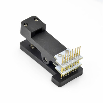
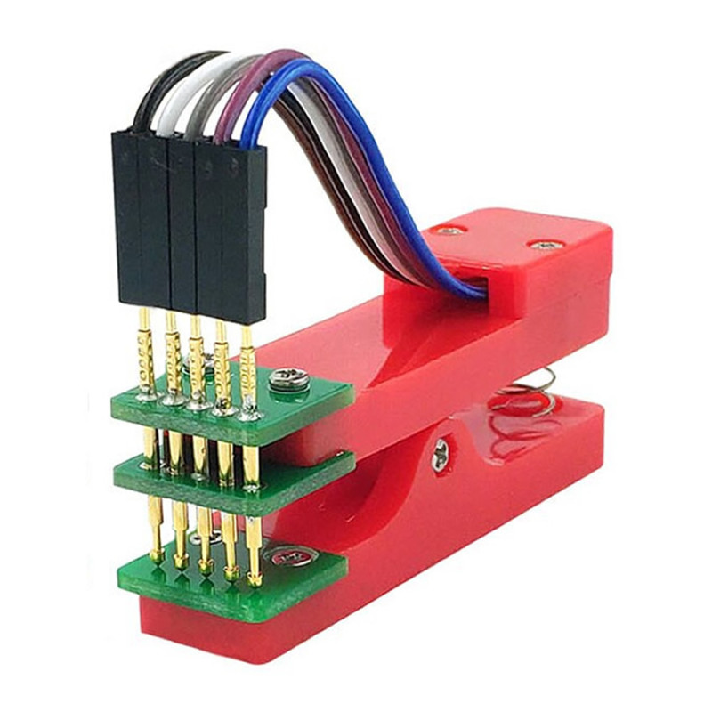
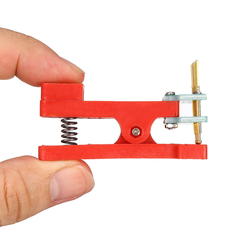
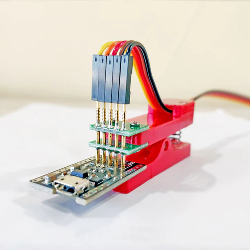
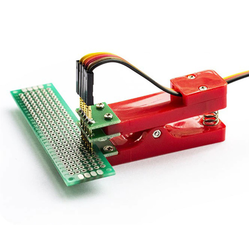
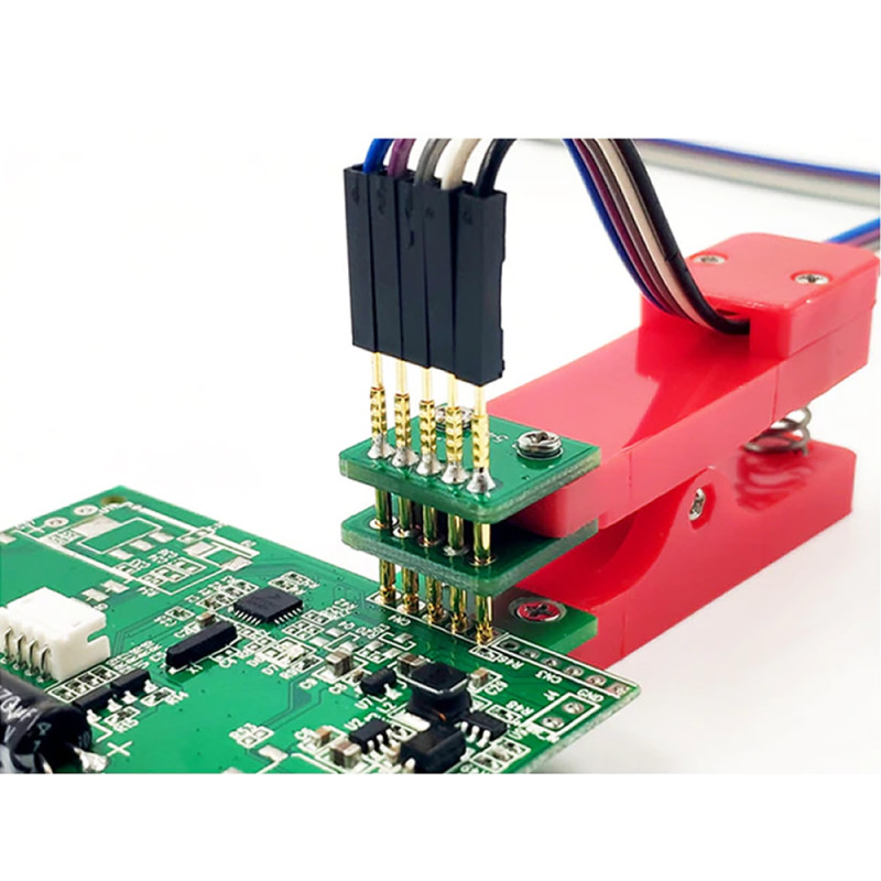
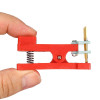
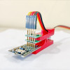
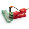
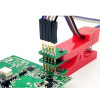
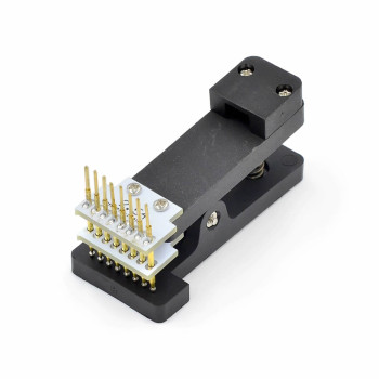
The 5 Pin Programming Fixture is a spring clamp connection tool for solderless, fast and easy firmware loading to the ICs on electronic boards. At its tip there are 5 pogo pins (spring test probes) in a single row at 2.54mm pitch. When the clamp is placed on the board edge, the spring presses the probes onto the board's programming pads; there is no need to solder a pin header or hold the probe by hand. When the job is done, the clamp is opened and the fixture is removed from the board.
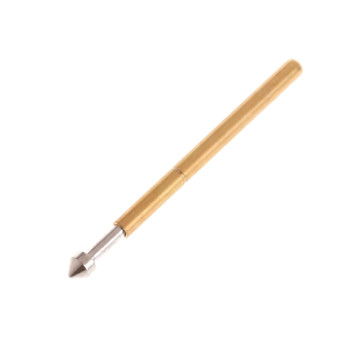
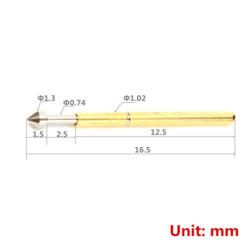
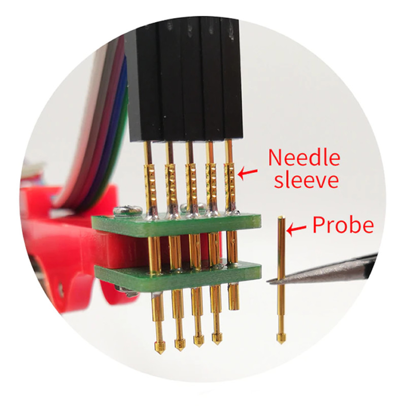
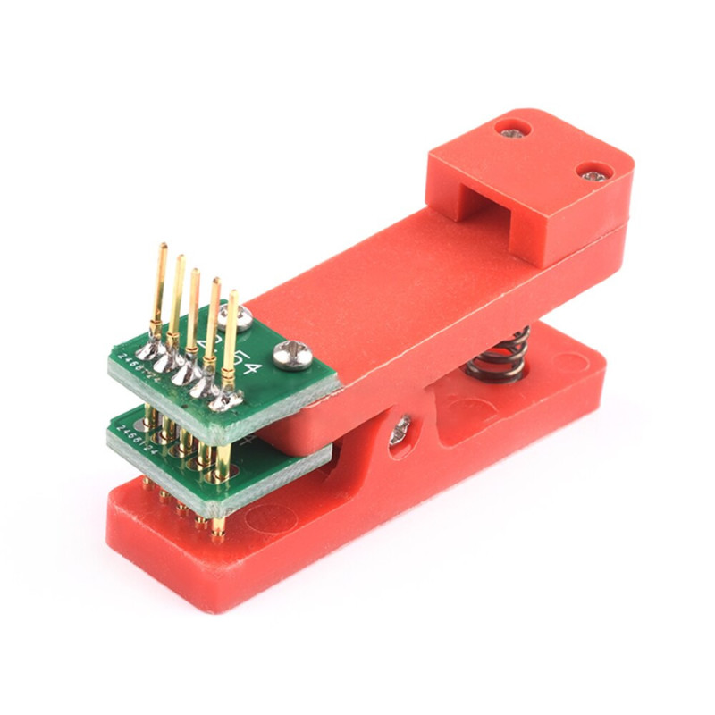
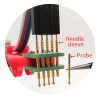
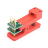
P75-E2 pointed pogo pins are used as the programming probe; the probes are soldered to the pin-mounted PCBs at the front. There are 5 male pin ends at 2.54mm pitch on top of the fixture; the supplied 5-pin 30cm female-female dupont cable plugs onto these ends and goes to the programmer. The removable cable collector groove keeps the cable tidy on top of the clamp.
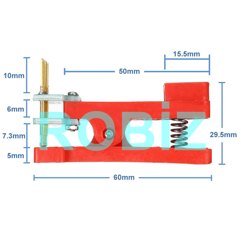
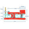
The spring and the pogo pins on the fixture can be replaced. For special needs with a different pin count or pin pitch, the pin-mounted PCBs at the front have a replaceable design. It suits mass production, testing and repair work where the same board is programmed many times. The fixture with its red plastic body measures 29.5mm x 60mm and weighs 25gr.
Key features:
Solderless connection: 5 pogo pins are spring pressed onto the board's programming pads; firmware is loaded without soldering a pin header, and the board stays clean.
Spring clamp, hands free: Once placed on the board edge the clamp holds by itself; there is no need to press the probe by hand while programming, and attaching or removing takes seconds.
Single row 2.54mm, 5 lines: The 5 probes are in a single row at 2.54mm pitch; they fit programming connections that use at most 5 lines, such as SWD (VCC, GND, SWDIO, SWCLK, NRST), PIC ICSP (MCLR, VDD, VSS, PGD, PGC) and UART (VCC, GND, TX, RX).
Replaceable parts: The spring, the P75-E2 pogo pins and the pin-mounted PCBs at the front can be replaced; a worn probe is renewed, and the PCB is changed for a different pin layout.
Cable included: The package contains a 5-pin 30cm female-female dupont cable; it plugs onto the 5 male pin ends on top of the fixture and stays tidy on the clamp with the cable collector groove.
Features:
- Product type: Spring clamp pogo pin programming and test fixture
- Number of pins: 5, single row
- Pin pitch: 2.54mm
- Pogo pin: P75-E2 pointed (conical) tip, soldered to the PCB
- Pin receptacle model: R75-3W
- Probe stroke (spring travel): approximately 2.5mm
- Holding method: Spring clamp; clips onto the board edge, no need to hold by hand
- Cable connection: A 5-pin female dupont cable plugs onto the 5 male pin ends at 2.54mm pitch on top of the fixture
- Replaceable parts: Spring, pogo pins, pin-mounted PCBs at the front
- Cable management: Removable cable collector groove
- Connection: Solderless, clips on and off the board
- Compatible programmers: Programmers, debuggers and USB-TTL converters with male pin outputs (e.g. ST-LINK V2; pin order is matched with the cable)
- Compatible ICs: ARM (STM32 etc.), PIC, Atmel AVR and other boards with single row 2.54mm pitch programming pads using at most 5 lines
- Material: Plastic / Metal (plastic clamp body, metal pogo pins and spring)
- Colour: Red
- Probe tip diameter: approximately 1.3mm (P75-E2)
- Cable length: 30cm (5-pin female-female dupont)
- Dimensions: 29.5mm x 60mm
- Weight: 25gr
Usage information:
- Identify the order of the 5 programming pads on the target board (e.g. VCC, GND, SWDIO, SWCLK, RESET) and connect each wire of the dupont cable to the programmer pin with the same name; note the cable colours.
- Open the clamp, place the board edge in its jaw, align the 5 probes exactly over the pads and release; the spring presses the probes onto the pads.
- Verify the connection in the programmer software and start the upload; when finished, open the clamp and remove the fixture. In mass production the same alignment is repeated on each board.
Applications:
- Firmware loading to boards in mass production
- Firmware loading and debugging of ARM (STM32 etc.) boards via SWD
- Programming PIC microcontrollers via ICSP
- Connecting to the 5-line programming pads of Atmel AVR microcontrollers
- Firmware loading and console access over UART (serial port)
- Temporary connection to boards without a soldered pin header
- Board testing, calibration and serial number writing on production lines
- Picking up signals from board pads during repair and troubleshooting
- Measurements on pads with a logic analyzer
Precautions:
- The pads on the target board must be in a single row at 2.54mm pitch. It is not suitable for 1.27mm pitch or double row (e.g. 2x5) programming connections.
- The classic 6-line AVR ISP connection (MISO, MOSI, SCK, RESET, VCC, GND) does not fit on 5 probes; on AVR boards the programming pad layout must use at most 5 lines.
- The programmer is not included; the fixture only provides the connection between the board and the programmer.
- Do not reverse the power (VCC) and ground (GND) lines; compare the cable order with the target board's pinout before connecting.
- Do not force the probes by sliding them sideways over the pads; the pointed tips may bend. A worn or bent pogo pin can be replaced.
- The board thickness the clamp can grip and the distance of the pads from the board edge are limited; on boards with pads far from the edge, the probes may not reach the pads.
Package contents:
- 1 Piece 5 Pin Programming Fixture
- 1 Piece 5-pin 30cm female-female dupont cable
- Note: The programmer (e.g. ST-LINK) is not included in the package.