- Stok Durumu: Stok Var
- Marka: OEM
- SKU: RBZ.101.584
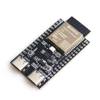
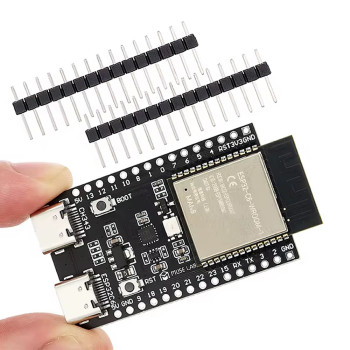
ESP32-S3-DevKitC-1 N16R8 Wifi Bluetooth 5 Module Development Board
ESP32-S3-N16R8 32 Bit Dual Core 240Mhz 8Mb Psram 16Mb Flash 36x IO Ws2812b Rgb Led Dual Type C Usb Uart Spi Adc Touch
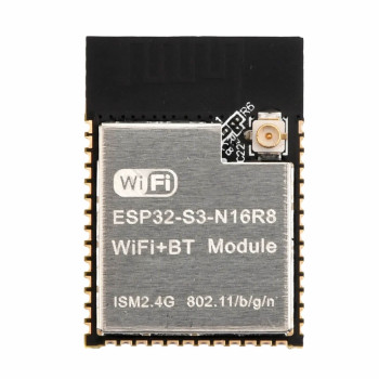
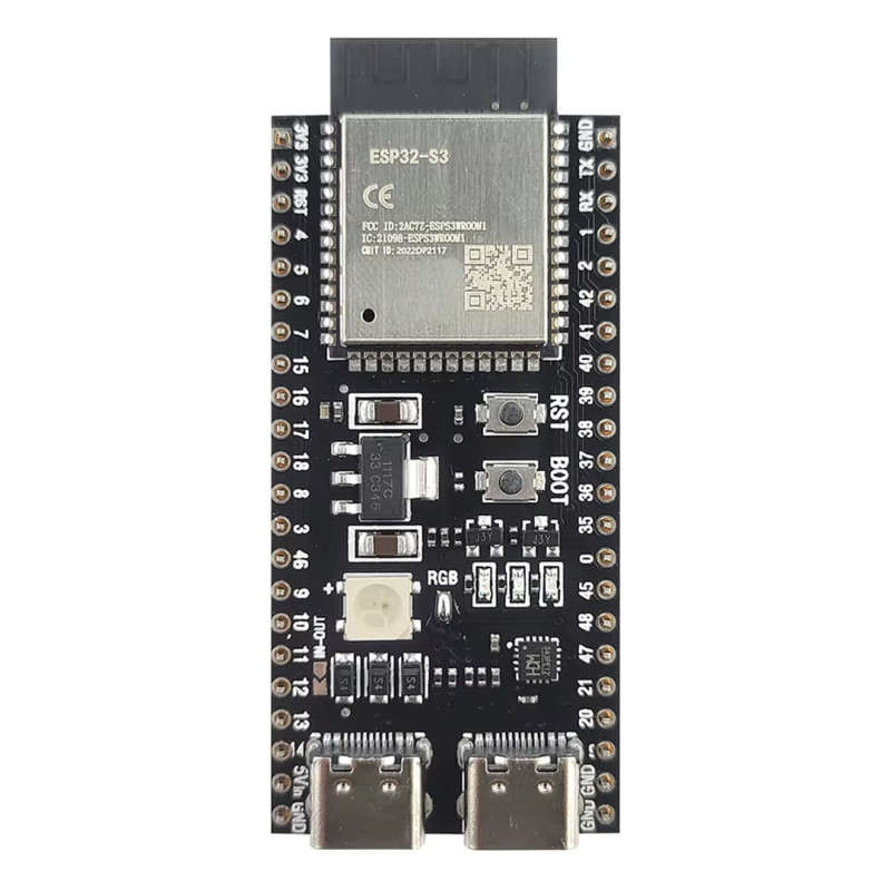
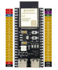
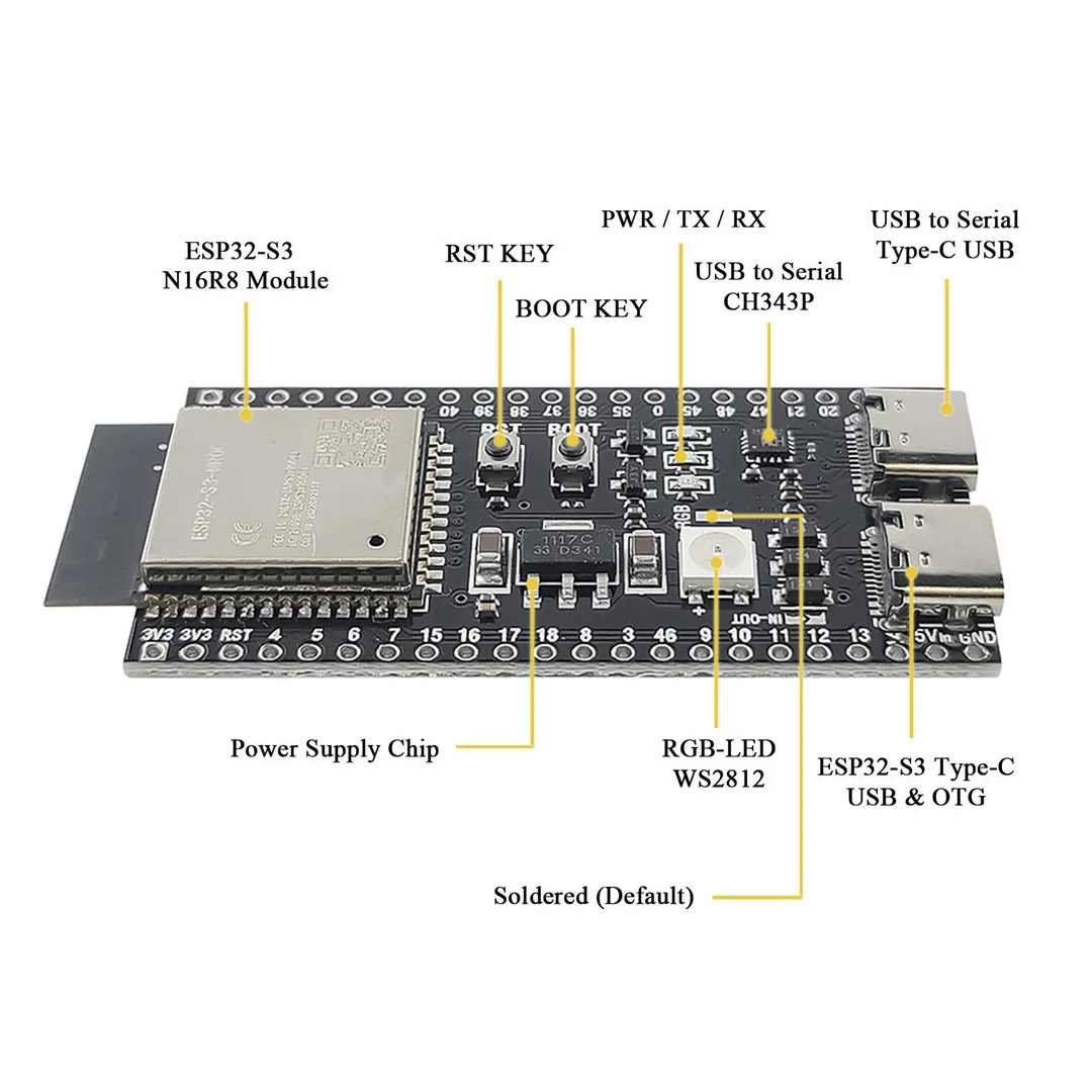
ESP32-S3-DevKitC-1 N16R8 is a 44-pin Wi-Fi and Bluetooth 5 (LE) development board with the DevKitC-1 pin layout, built with the Espressif ESP32-S3-WROOM-1-N16R8 module. The module contains a dual-core 32 bit Xtensa LX7 processor running at up to 240MHz, 512KB SRAM, 16MB Quad SPI Flash and 8MB Octal SPI PSRAM. Thanks to the large PSRAM, memory hungry tasks such as camera images, display buffers, audio and AI models can run on the board.
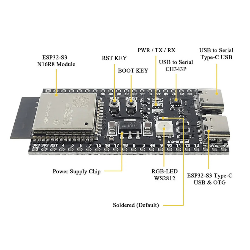
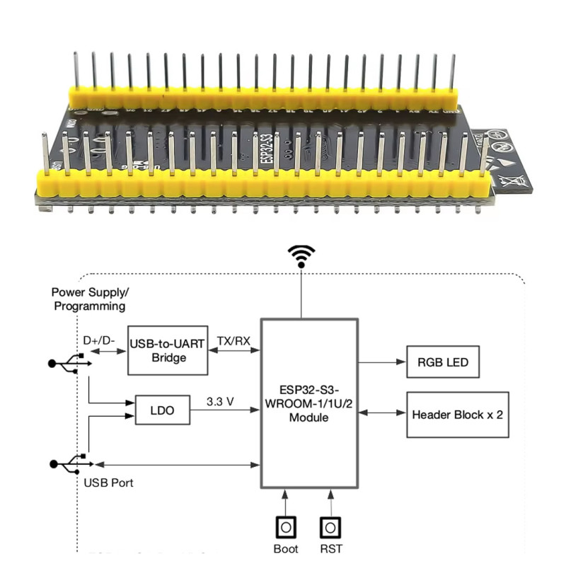
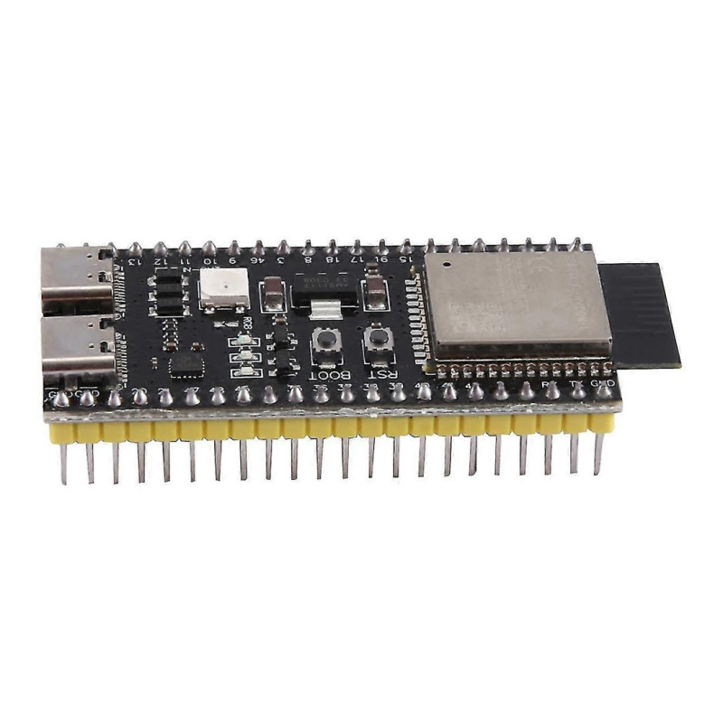
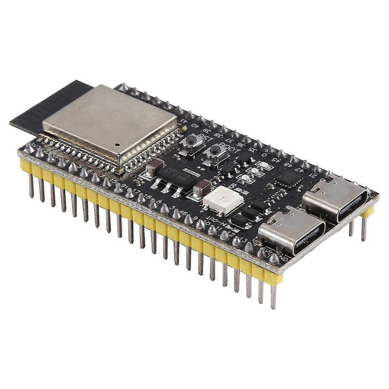
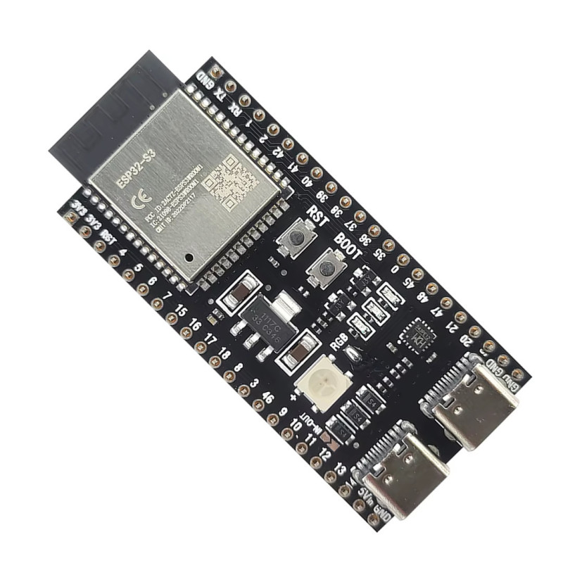
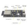
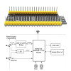
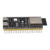
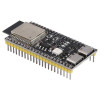
The board has two USB Type-C sockets: one for programming, serial port and power through the CH343P USB - serial converter, the other for the ESP32-S3's own USB OTG port (GPIO19 / GPIO20). On the board there is a WS2812 addressable RGB LED on GPIO48, power, TX and RX indicator LEDs, RST and BOOT buttons and a 3.3V regulator with 1A output. The 2 x 22 pin headers come soldered and fit a breadboard with 2.54mm pitch.
The board is programmed with Arduino IDE, ESP-IDF, MicroPython and CircuitPython. Wi-Fi 802.11b/g/n (2.4GHz) and Bluetooth 5 (LE) can be used at the same time; with SPI, I2C, I2S, UART, camera and LCD interfaces, TWAI (CAN), ADC and touch inputs it suits IoT devices, smart home control, camera and audio projects and robot control.
Key features:
16MB Flash and 8MB PSRAM: 16MB Flash for large programs, file system and OTA updates; 8MB Octal SPI PSRAM for camera images, display buffers and AI models.
Dual USB Type-C: Programming and serial port through CH343P and the ESP32-S3's native USB OTG port are on separate sockets; the native USB works as a USB device (keyboard, mouse, serial port) or for JTAG debugging over USB.
Powerful dual core: Two Xtensa LX7 cores running at up to 240MHz with vector instructions accelerate AI tasks such as voice recognition and image processing.
On-board RGB LED: The WS2812 addressable RGB LED on GPIO48 needs no extra parts for a first test or status indication.
DevKitC-1 pin layout: The 2 x 22 pin headers follow the same pin order as schematics, expansion boards and examples written for DevKitC-1.
Features:
- Product type: ESP32-S3 Wi-Fi + Bluetooth 5 (LE) development board, DevKitC-1 pin layout, 44 pins
- Module: ESP32-S3-WROOM-1-N16R8, PCB antenna
- Processor: Xtensa 32 bit LX7 dual core, up to 240MHz
- Internal memory: 512KB SRAM, 384KB ROM, 16KB RTC SRAM
- Flash: 16MB (Quad SPI)
- PSRAM: 8MB (Octal SPI)
- Wi-Fi: 802.11b/g/n, 2.4GHz, up to 150Mbps
- Bluetooth: Bluetooth 5 (LE), Bluetooth mesh, up to 2Mbps
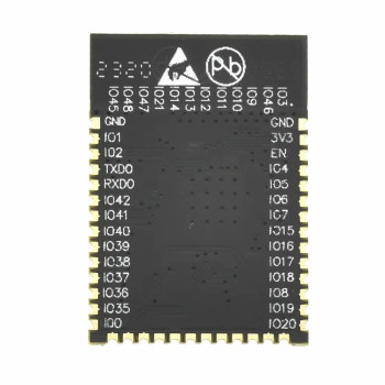
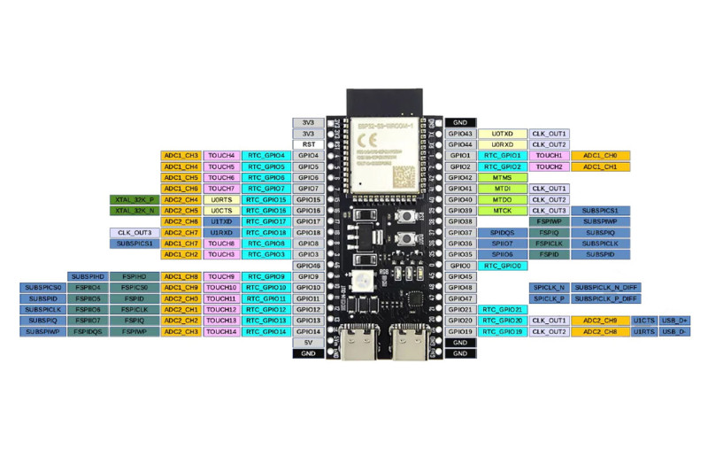
- GPIO: 36 GPIO (module); GPIO35, GPIO36, GPIO37 are connected to the Octal PSRAM
- Peripherals: SPI, I2C, I2S, UART, LCD and camera interface, LED PWM, MCPWM, SD/MMC, TWAI (CAN), ADC, touch input, temperature sensor
- USB - serial converter: CH343P, Type-C socket (programming, serial port, power)
- Native USB: Second Type-C socket, USB OTG (GPIO19 D-, GPIO20 D+), USB Serial/JTAG
- Power supply: USB Type-C 5V or 5V pin; on-board 3.3V regulator with 1A output
- RGB LED: WS2812 addressable RGB LED (GPIO48)
- Indicator LEDs: Power, TX and RX
- Buttons: RST (reset) and BOOT
- Security: AES, SHA, RSA, RNG; Secure boot, Flash encryption, digital signature, HMAC; 4096 bit OTP
- Software support: Arduino IDE, ESP-IDF, MicroPython, CircuitPython
- Operating temperature: -40°C - 65°C (N16R8 module)
- Pin header: 2 x 22 pin male header, 2.54mm pitch, soldered
- Colour: Black PCB
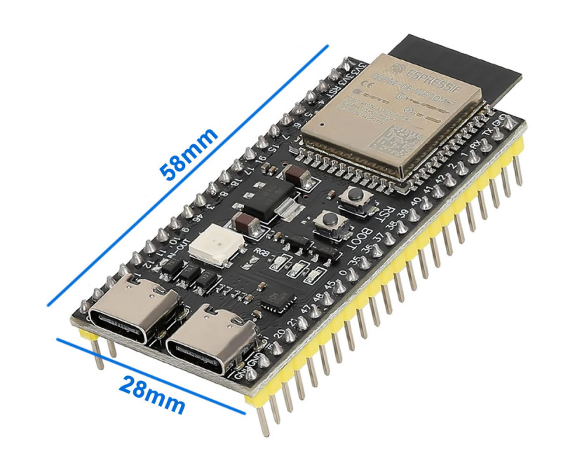
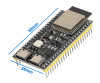
- Dimensions: approx. 63.5mm x 28mm
- Weight: approx. 12gr
Usage information:
- For programming, connect the Type-C socket wired to the CH343P converter (on the right) to the computer; the CH343 driver must be installed on Windows. If the upload does not start automatically, hold the BOOT button, press and release RST; the board starts in programming mode.
- In Arduino IDE select "ESP32S3 Dev Module" as the board; set Flash Size to "16MB (128Mb)" and PSRAM to "OPI PSRAM". If the PSRAM setting is not enabled, the 8MB PSRAM cannot be used.
- The on-board RGB LED is a WS2812 on GPIO48; it is driven with an addressable LED library, not with a plain digitalWrite.
- The other Type-C socket is the ESP32-S3's native USB port; it is used for USB CDC serial port, USB HID device or JTAG debugging over USB.
Application areas:
- IoT sensor, data logging and remote monitoring devices
- Camera and image streaming projects
- AI applications: face recognition, object detection
- Voice recognition, voice command and audio playback projects
- Robot, vehicle and drone controller board
- Automation: smart home, lighting and remote control systems
- Control panels and interfaces with displays (LCD / TFT)
- Building USB keyboard, mouse and MIDI devices
- Bluetooth LE sensors and wearable devices
- Education, laboratory and prototype development
Precautions:
- On the N16R8 module GPIO35, GPIO36 and GPIO37 are connected to the Octal PSRAM; do not use these pins for other purposes.
- GPIO pins are 3.3V logic; do not connect 5V signals directly.
- GPIO0, GPIO3, GPIO45 and GPIO46 are boot strapping pins; do not force them with external circuits at power up; the board may stay in programming mode or fail to boot (GPIO45 selects the flash supply voltage).
- The maximum operating temperature of the N16R8 module with Octal PSRAM is 65°C; leave ventilation in closed and hot enclosures.
- The RGB LED on this board is on GPIO48. In examples written for Espressif's v1.1 boards the LED is on GPIO38; change the pin number to 48 in the example code.
Package contents:
- 1 x ESP32-S3-DevKitC-1 N16R8 Development Board
- 2 x 22 pin male header ( Assembled )
- Note: USB Type-C cable is not included in the package.
Usb driver: The CH343SER.EXE file must be downloaded through Google and installed.
wch-ic.com/products/CH343.html
Software support:
- docs.espressif.com/projects/esp-idf/en/latest/esp32s3/get-started/index.html
- docs.espressif.com/projects/arduino-esp32/en/latest/getting_started.html#about-arduino-esp32
- docs.micropython.org/en/latest/esp32/quickref.html
- github.com/microrobotics/ESP32-S3-N16R8/blob/main/ESP32-S3-N16R8_User_Guide.pdf
- 99tech.com.au/mx-m/esp32/esp32-s3-yd_schematics.pdf
- espressif.com/sites/default/files/documentation/esp32-s3-wroom-1_wroom-1u_datasheet_en.pdf
- tasmota.github.io/docs/
- github.com/vcc-gnd/YD-ESP32-S3
- circuitpython.org/board/yd_esp32_s3_n16r8/
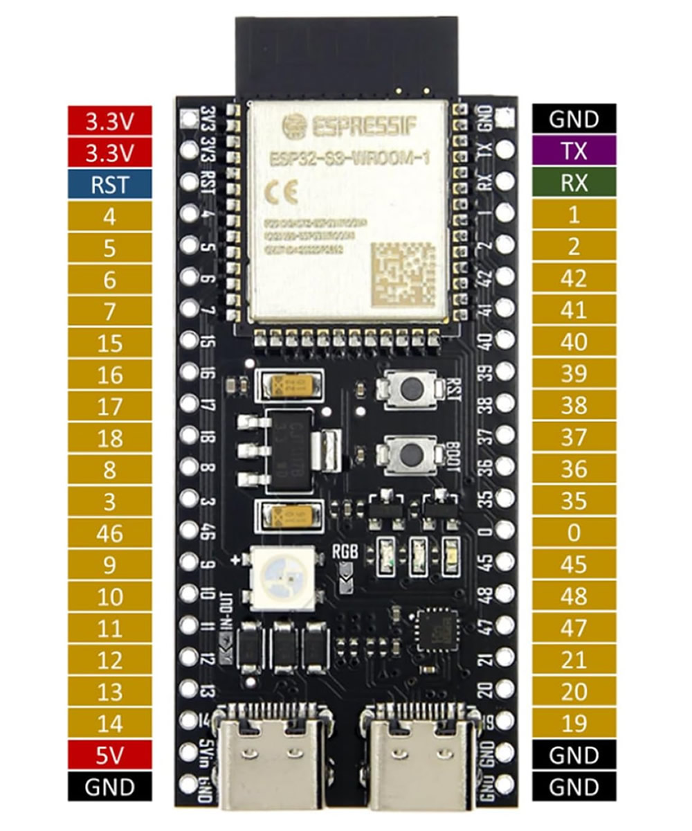
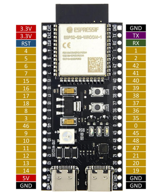
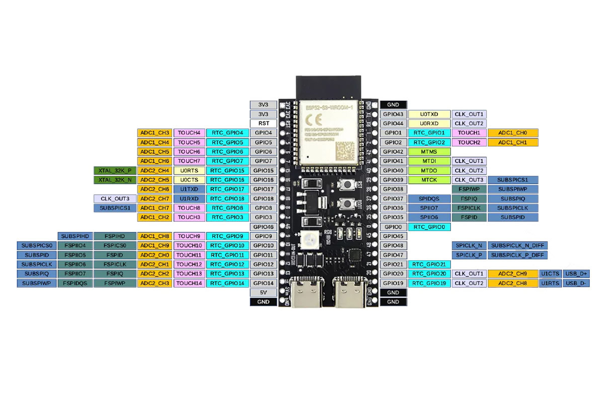
Pin description table:
| No | Pin | Type | Pin Function |
|---|---|---|---|
| 1 | 3V3 | P | 3.3V |
| 2 | 3V3 | P | 3.3V |
| 3 | RST | I | EN |
| 4 | 4 | I/O/T | RTC_GPIO4, GPIO4, TOUCH4, ADC1_CH3 |
| 5 | 5 | I/O/T | RTC_GPIO5, GPIO5, TOUCH5, ADC1_CH4 |
| 6 | 6 | I/O/T | RTC_GPIO6, GPIO6, TOUCH6, ADC1_CH5 |
| 7 | 7 | I/O/T | RTC_GPIO7, GPIO7, TOUCH7, ADC1_CH6 |
| 8 | 15 | I/O/T | RTC_GPIO15, GPIO15, U0RTS, ADC2_CH4, XTAL_32K_P |
| 9 | 16 | I/O/T | RTC_GPIO16, GPIO16, U0CTS, ADC2_CH5, XTAL_32K_N |
| 10 | 17 | I/O/T | RTC_GPIO17, GPIO17, U1TXD, ADC2_CH6 |
| 11 | 18 | I/O/T | RTC_GPIO18, GPIO18, U1RXD, ADC2_CH7, CLK_OUT3 |
| 12 | 8 | I/O/T | RTC_GPIO8, GPIO8, TOUCH8, ADC1_CH7, SUBSPICS1 |
| 13 | 3 | I/O/T | RTC_GPIO3, GPIO3, TOUCH3, ADC1_CH2 |
| 14 | 46 | I/O/T | GPIO46 |
| 15 | 9 | I/O/T | RTC_GPIO9, GPIO9, TOUCH9, ADC1_CH8, FSPIHD, SUBSPIHD |
| 16 | 10 | I/O/T | RTC_GPIO10, GPIO10, TOUCH10, ADC1_CH9, FSPICS0, FSPIIO4, SUBSPICS0 |
| 17 | 11 | I/O/T | RTC_GPIO11, GPIO11, TOUCH11, ADC2_CH0, FSPID, FSPIIO5, SUBSPID |
| 18 | 12 | I/O/T | RTC_GPIO12, GPIO12, TOUCH12, ADC2_CH1, FSPICLK, FSPIIO6, SUBSPICLK |
| 19 | 13 | I/O/T | RTC_GPIO13, GPIO13, TOUCH13, ADC2_CH2, FSPIQ, FSPIIO7, SUBSPIQ |
| 20 | 14 | I/O/T | RTC_GPIO14, GPIO14, TOUCH14, ADC2_CH3, FSPIWP, FSPIDQS, SUBSPIWP |
| 21 | 5V | P | 5V |
| 22 | G | G | Ground |
| No | Pin | Type | Pin Function |
|---|---|---|---|
| 1 | G | G | Ground |
| 2 | TX | I/O/T | U0TXD, GPIO43, CLK_OUT1 |
| 3 | RX | I/O/T | U0RXD, GPIO44, CLK_OUT2 |
| 4 | 1 | I/O/T | RTC_GPIO1, GPIO1, TOUCH1, ADC1_CH0 |
| 5 | 2 | I/O/T | RTC_GPIO2, GPIO2, TOUCH2, ADC1_CH1 |
| 6 | 42 | I/O/T | MTMS and GPIO42 |
| 7 | 41 | I/O/T | MTDI, GPIO41, CLK_OUT1 |
| 8 | 40 | I/O/T | MTDO, GPIO40, CLK_OUT2 |
| 9 | 39 | I/O/T | MTCK, GPIO39, CLK_OUT3, SUBSPICS1 |
| 10 | 38 | I/O/T | GPIO38, FSPIWP, SUBSPIWP |
| 11 | 37 | I/O/T | SPIDQS, GPIO37, FSPIQ, SUBSPIQ |
| 12 | 36 | I/O/T | SPIIO7, GPIO36, FSPICLK, SUBSICLK, SUBSPICLK |
| 13 | 35 | I/O/T | SPIIO6, GPIO35, FSPID, SUBSPID |
| 14 | 0 | I/O/T | RTC_GPIO, GPIO0 |
| 15 | 45 | I/O/T | GPIO45 |
| 16 | 48 | I/O/T | GPIO48, SPPLK_N, SUBSPICLK_N_DIFF, RGB LED |
| 17 | 47 | I/O/T | GPIO47, SPPLK_P, SUBSPICLK_P_DIFF |
| 18 | 21 | I/O/T | RTC_GPIO21, GPIO21 |
| 19 | 20 | I/O/T | RTC_GPIO20, GPIO20, U1CTS, ADC2_CH9, CLK_OUT1, USB_D+ |
| 20 | 19 | I/O/T | RTC_GPIO19, GPIO19, U1RTS, ADC2_CH8, CLK_OUT2, USB_D- |
| 21 | G | G | Ground |
| 22 | G | G | Ground |
I: Input
O: Output
T: Indicates the need for a pull up resistor.
Wifi test example:
It makes the Esp module create the wifi network. You can connect to this network with a phone or pc. When you go to the address 192.168.4.1 a button appears. The page is served from inside the espboard. Each time you press the button, the RGB LED on the board turns on/off.
Wifi network name: ESP32S3_TEST
Password: 12345678
Connection address: When you go to the address 192.168.4.1 a button appears. Each time you press the button the RGB LED turns on/off
#include <WiFi.h>
#include <WebServer.h>
#include <Adafruit_NeoPixel.h>
#define WS_PIN 48
#define WS_COUNT 1
Adafruit_NeoPixel ws(WS_COUNT, WS_PIN, NEO_GRB + NEO_KHZ800);
WebServer server(80);
const char* ssid = "ESP32S3_TEST";
const char* password = "12345678";
bool ledState = false;
void handleRoot() {
String html = "<!DOCTYPE html><html><head><meta name='viewport' content='width=device-width, initial-scale=1'>";
html += "<h2>ESP32-S3 WIFI TEST</h2>";
html += "<p>RGB LED DURUM: ";
html += (ledState ? "ACIK" : "KAPALI");
html += "</p>";
html += "<a href='/toggle'><button style='font-size:30px;'>TOGGLE</button></a>";
html += "</body></html>";
server.send(200, "text/html", html);
}
void handleToggle() {
ledState = !ledState;
if (ledState)
ws.setPixelColor(0, ws.Color(0, 150, 255));
else
ws.setPixelColor(0, ws.Color(0, 0, 0));
ws.show();
server.sendHeader("Location", "/");
server.send(303);
}
void setup() {
Serial.begin(115200);
ws.begin();
ws.setBrightness(40);
ws.show();
WiFi.mode(WIFI_AP);
WiFi.softAP(ssid, password);
IPAddress IP = WiFi.softAPIP();
Serial.print("AP IP: ");
Serial.println(IP);
server.on("/", handleRoot);
server.on("/toggle", handleToggle);
server.begin();
Serial.println("WIFI TEST HAZIR");
}
void loop() {
server.handleClient();
}