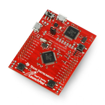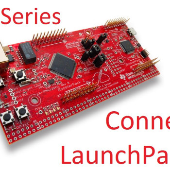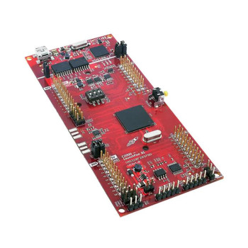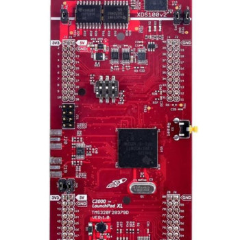
- Stok Durumu: Stok Var
- Marka: Texas Instruments
- SKU: RBZ.200.036
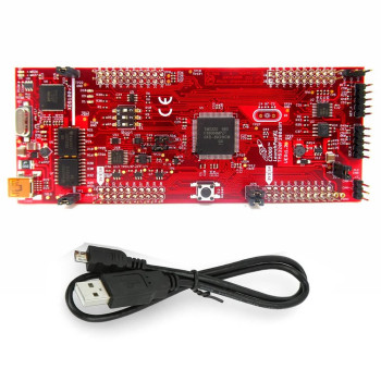
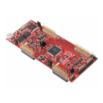
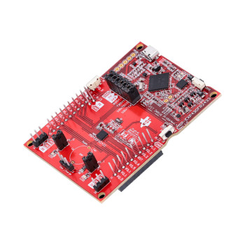
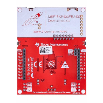
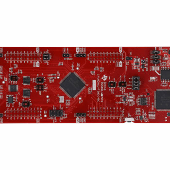
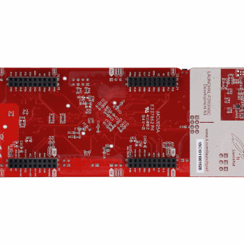
MSP-EXP430G2ET
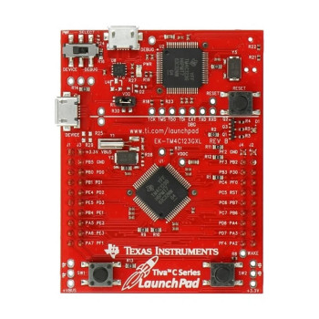
MSP430 LaunchPad Development Board MSP430G2553IN20 16 MHz Mcro Usb Ezfet Debug Probe Programmer Emulator
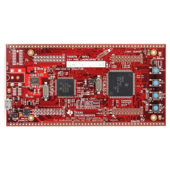
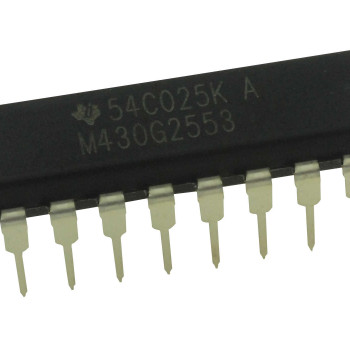
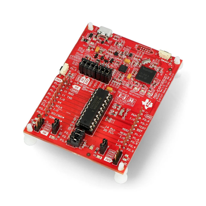
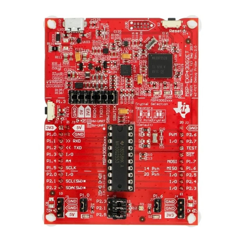
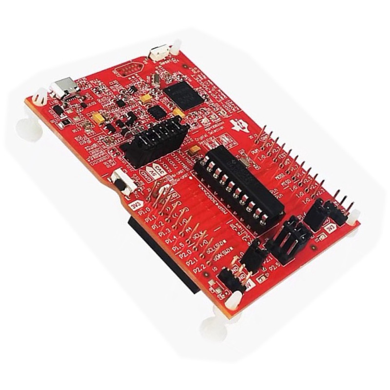
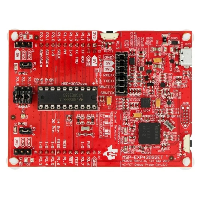
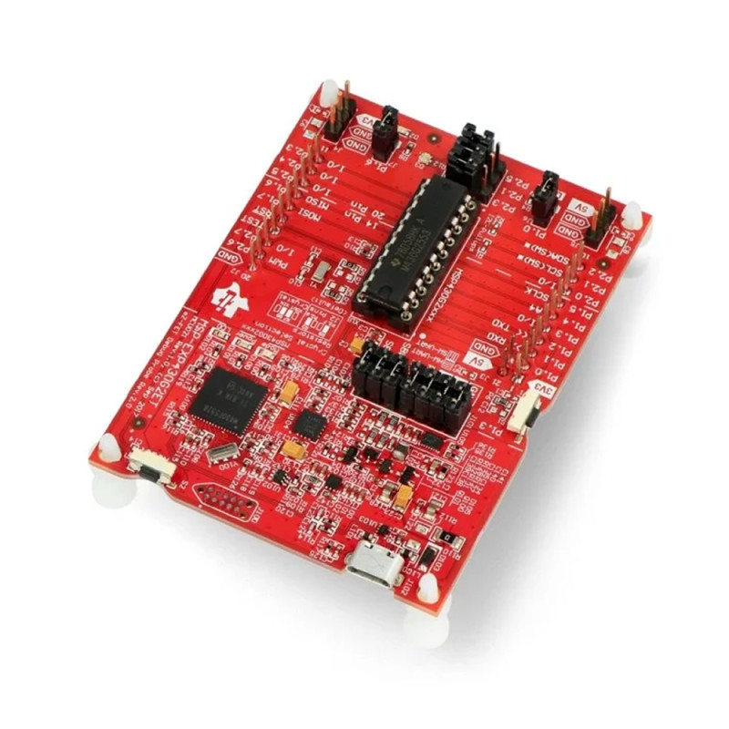
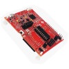
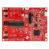
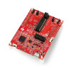
The MSP-EXP430G2ET is the original Texas Instruments LaunchPad development kit for the low-power MSP430G2 (Value Line) microcontrollers. The board ships with an MSP430G2553IN20 microcontroller in its socket: 16-bit RISC core, up to 16MHz clock, 16KB Flash, 512B SRAM, 8-channel 10-bit ADC, UART, SPI and I2C. The microcontroller is preloaded with a sample program; when the board is plugged into USB it starts with the red and green LEDs.
The upper part of the board carries the on-board eZ-FET debug probe. Without a separate programmer you program, debug step by step and measure energy in real time with EnergyTrace over Micro USB; the same USB connection also opens a virtual COM port (backchannel UART) on the PC. The signals between the eZ-FET and the target area can be separated with the J101 isolation jumper block, so you can measure current or use the eZ-FET to program another MSP430 circuit.
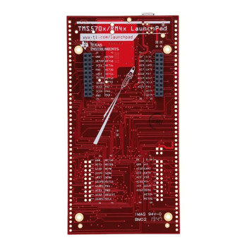
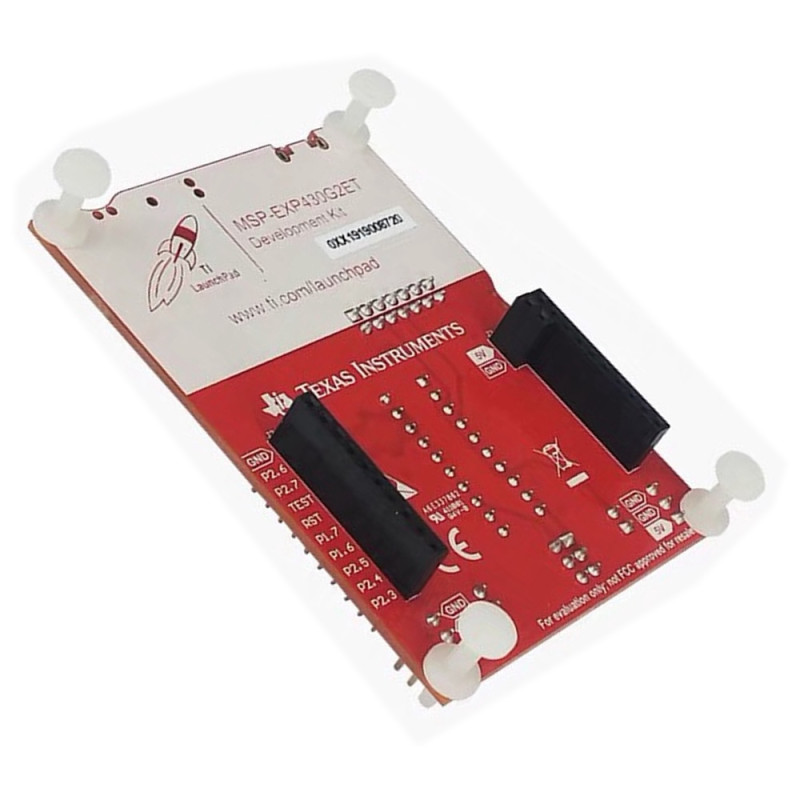
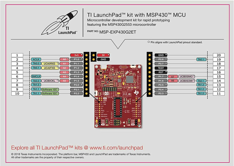
The 20-pin DIP socket accepts MSP430G2xx1, G2xx2, G2xx3 and MSP430F20xx microcontrollers in 14 and 20-pin PDIP packages: you can remove the programmed chip from the socket and place it in your own circuit. The pin headers follow the 20-pin LaunchPad standard and are compatible with BoosterPack plug-in boards. The board is programmed free of charge with Code Composer Studio and IAR Embedded Workbench.
Key features:
On-board eZ-FET debugger: No separate tool is needed for programming and debugging; plug the Micro USB cable into the PC, load code with Code Composer Studio or IAR, set breakpoints and watch variables.
EnergyTrace energy measurement: The energy used by the application is measured in real time during debugging; comparing low-power modes and extending battery life in battery-powered devices becomes easy.
Socketed DIP microcontroller: The MSP430G2553IN20 sits in a removable 20-pin socket. With the same socket, MSP430G2xx and MSP430F20xx chips in 14 and 20-pin PDIP packages can be programmed and moved to your own circuit.
Backchannel UART: The eZ-FET passes the USCI_A0 UART of the microcontroller to the PC as a virtual COM port over USB; data is sent and received with a terminal program without a separate USB-serial converter.
Isolation jumper block and BoosterPack: The J101 jumpers separate the 5V, 3V3, RXD, TXD, RST and TST lines; current is measured by connecting an ammeter in place of the 3V3 jumper. BoosterPack boards plug into the 20-pin LaunchPad headers.
Features:
- Product type: MSP430 LaunchPad development kit (original Texas Instruments)
- Model: MSP-EXP430G2ET
- Installed microcontroller: MSP430G2553IN20 (20-pin PDIP, in socket, preloaded with sample program)
- Core and clock: 16-bit RISC, up to 16MHz
- Memory: 16KB Flash, 512B SRAM
- Analog: 8-channel 10-bit ADC, 8-channel comparator
- Timers: 2x 16-bit Timer_A (3 capture/compare registers)
- Communication: USCI_A (UART, IrDA, SPI), USCI_B (SPI, I2C)
- Inputs/outputs: 16 I/O pins (P1.0 - P1.7, P2.0 - P2.7)
- Debugger: On-board eZ-FET (Spy-Bi-Wire), EnergyTrace technology (EnergyTrace++ not supported)
- Backchannel UART: Virtual COM port over USB ("MSP Application UART1"), connected to USCI_A0
- Isolation jumper block (J101): GND, 5V, 3V3, RXD, TXD, RST, TST
- DIP socket: 14 and 20-pin PDIP; MSP430G2xx1, MSP430G2xx2, MSP430G2xx3 and MSP430F20xx
- Expansion: 20-pin LaunchPad standard, compatible with BoosterPack plug-in boards
- User interface: 1 user button (P1.3), 1 Reset button, 3 LEDs (red, green, yellow)
- Crystal: 32.768kHz (Y1); not connected to the microcontroller by default, connected by resistor selection
- Power: Micro-B USB 5V, on-board 3.3V regulator; external supply via header J4 (microcontroller 1.8V - 3.6V)
- Software: Code Composer Studio, IAR Embedded Workbench for MSP430 (EnergyTrace supported)
- Material and color: Red printed circuit board, plastic feet at the bottom corners
Usage information:
- Plug the board into the PC with the Micro USB cable; the eZ-FET drivers come with the Code Composer Studio or IAR installation. In the preloaded sample program, pressing the P1.3 button switches to live temperature mode; as the temperature moves away from the initial reference, the red or green LED glows brighter, and pressing P1.3 again recalibrates the reference.
- To use the backchannel UART, open the COM port named "MSP Application UART1" on the PC and set the speed to the UART setting of the microcontroller (the preloaded sample program sends at 9600bps, 8N1 using a Timer_A based software UART). RXD/TXD jumpers in horizontal position select the hardware UART, in vertical position the software UART on P1.1/P1.2.
- To measure the microcontroller current, remove the 3V3 jumper on J101 and connect an ammeter in its place. To program another MSP430 circuit, remove all jumpers on J101 and connect the 3.3V, GND, SBWTDIO (RST) and SBWTCK (TST) lines on the eZ-FET side to the target circuit.
Application areas:
- MSP430 and embedded software education, university laboratory courses
- Battery-powered low-power device prototypes
- Sensor reading, measurement and data logging applications
- Thermometer and temperature monitoring circuits
- Smart home control and remote monitoring trials
- Robot and motor control (with Timer_A PWM outputs)
- Wireless, display and sensor prototypes with BoosterPack
- Programming DIP MSP430 chips and placing them in your own circuit
- Programming and debugging other MSP430 boards via Spy-Bi-Wire
- Energy consumption measurement and battery life optimization with EnergyTrace
Precautions:
- The MSP430G2553 operates between 1.8V and 3.6V. When supplying external power through header J4 do not exceed 3.6V; do not apply 5V signals directly to the microcontroller pins.
- The socket supports only MSP430G2xx and MSP430F20xx chips in 14 and 20-pin PDIP packages. Insert the chip aligned to pin 1 of the socket; a chip inserted backwards will be damaged.
- The 32.768kHz crystal is not connected by default (its pins are shared with BoosterPack lines). To use it, R3 and R9 must be removed and R5 and R7 shorted.
- The board supports EnergyTrace, not EnergyTrace++. When programming another circuit with the eZ-FET, the capacitor on the target's RST/SBWTDIO line must not be larger than 2.2nF.
Package contents:
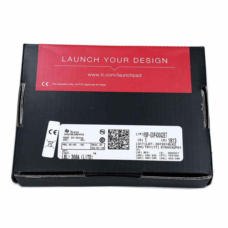
- 1 x MSP-EXP430G2ET LaunchPad Development Board
- 1 x MSP430G2553IN20 microcontroller, preloaded with sample program ( Assembled )
- 1 x Micro USB cable