- Stok Durumu: Stok Var
- Marka: STMicroelectronics
- SKU: RBZ.200.068
ST NUCLEO-G431RB
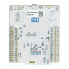
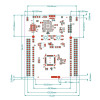
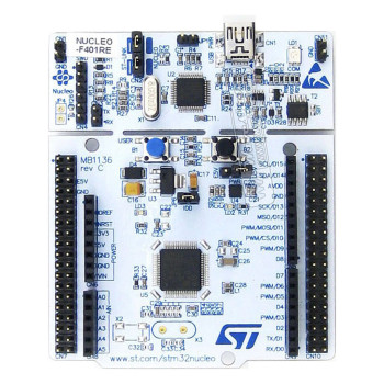
STM32 32 Bit 170MHz Arm Cortex M4 STM32G431RB Development Kit ST-LINK V2 Jtag Programmer Arduino Compatible
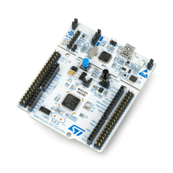
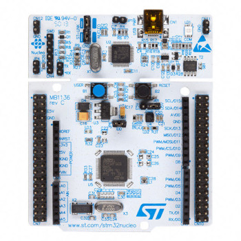
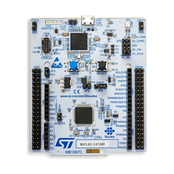
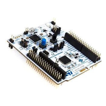
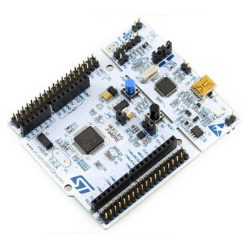
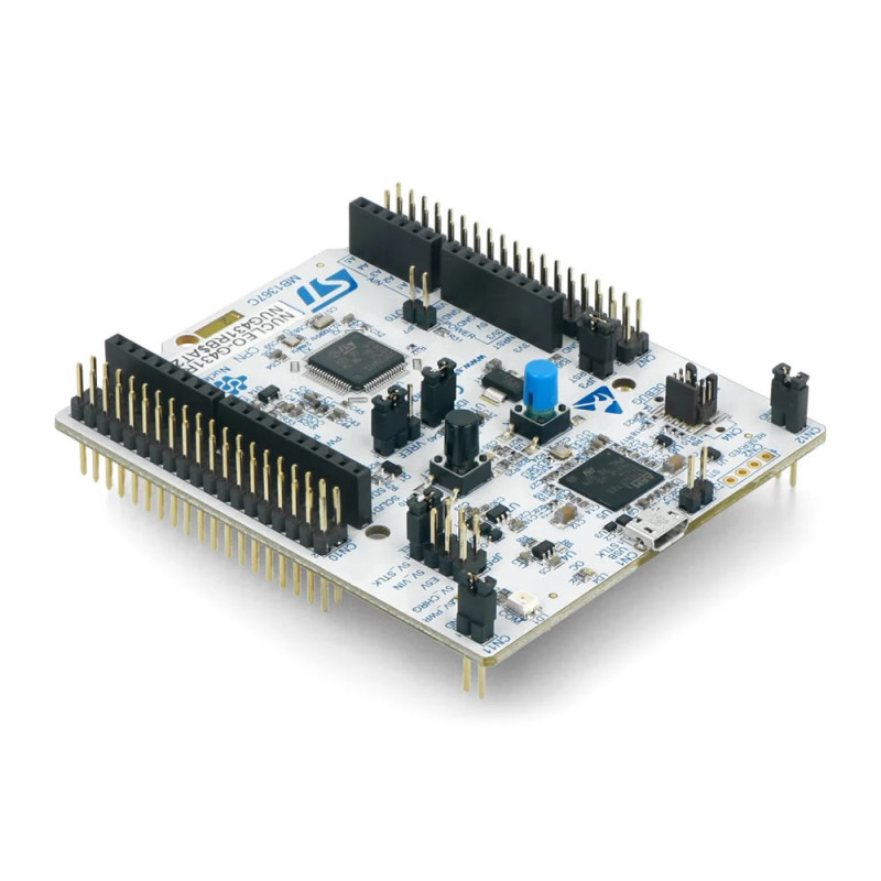
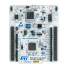
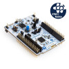
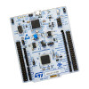
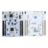
NUCLEO-G431RB is the original STM32G4 Nucleo-64 development board from STMicroelectronics (MB1367). It carries the STM32G431RBT6 microcontroller in an LQFP64 package: Arm Cortex-M4 core with FPU, 170MHz clock (213 DMIPS), 128KB Flash with ECC and 32KB SRAM (22KB SRAM + 10KB CCM SRAM). It is the entry member of the STM32G4 family; the CORDIC unit for trigonometric functions and the FMAC unit for filter calculations take load off the core in motor control and measurement applications.
The analog side of the board is rich: 2 fast 12-bit ADCs (0.25µs), 4 channels of 12-bit DAC, 4 fast comparators and 3 opamps usable in PGA mode are inside the chip. 2 advanced 8-channel timers dedicated to motor control generate PWM with dead time and emergency stop inputs; the flexible data rate FDCAN controller is ready for CAN FD communication.
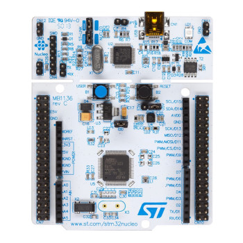
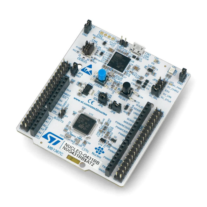
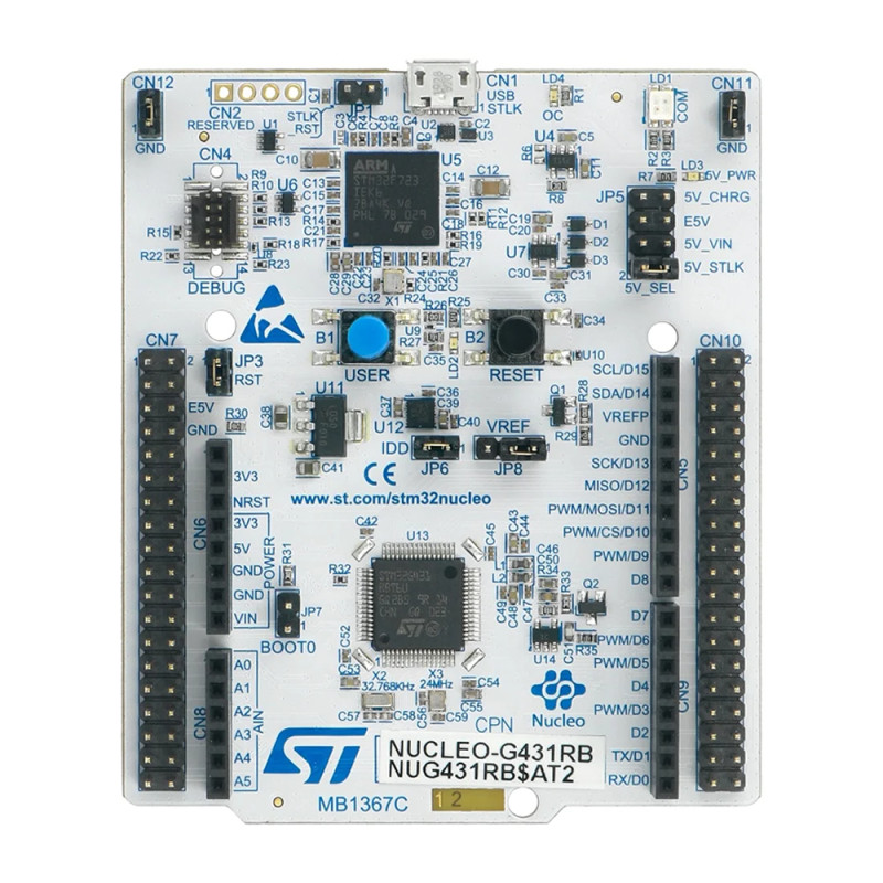
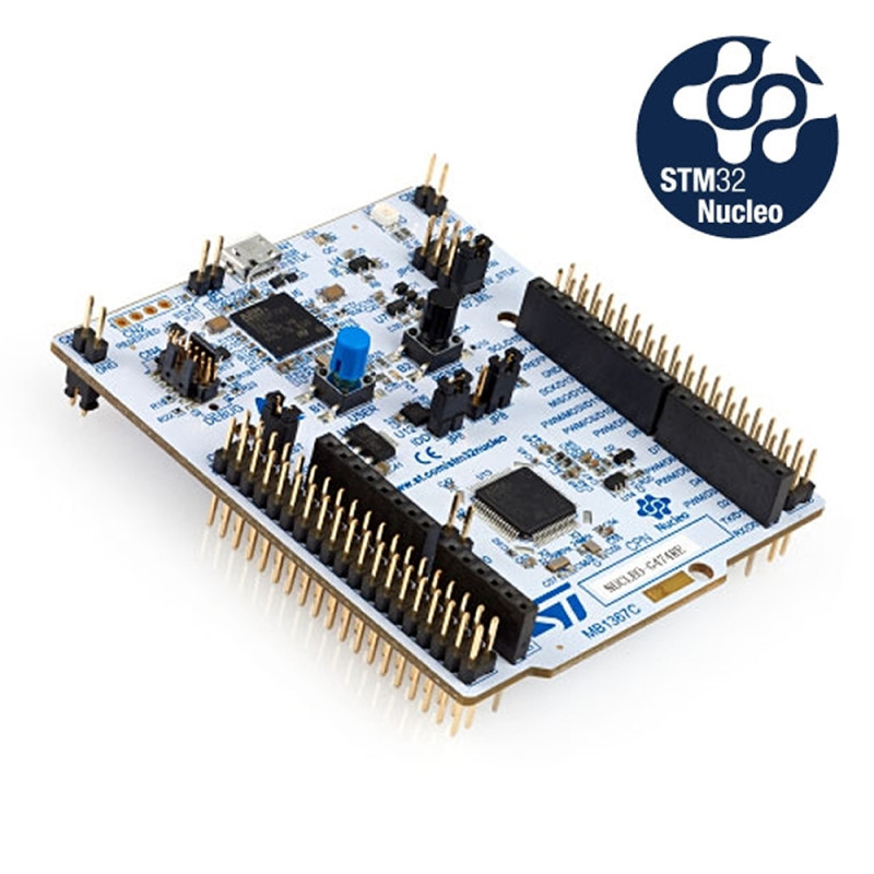
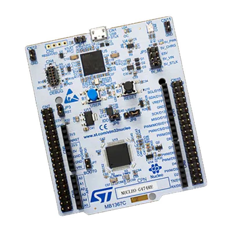
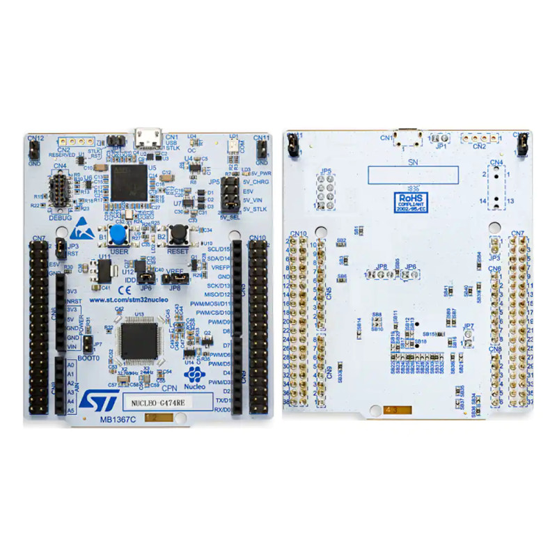
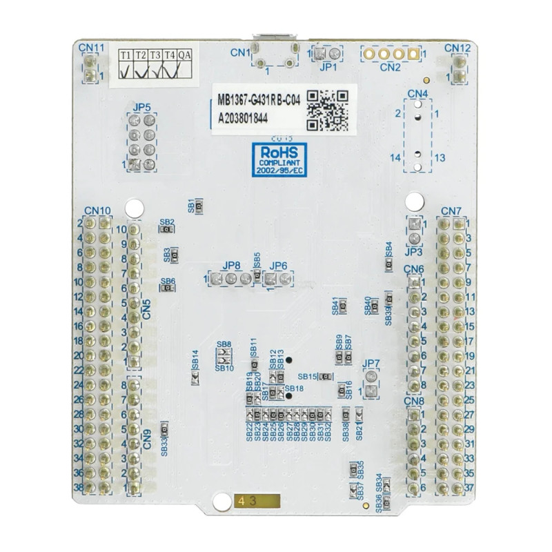
The STLINK-V3E programmer and debugger on the board needs no separate device: when connected to a computer with a Micro USB (Micro-B) cable it appears as a virtual COM port, a USB drive for drag and drop programming and a debug port. Arduino Uno V3 compatible female headers take shields, the ST morpho pin rows on both sides give access to all I/O pins. The board is powered from USB, the 7V - 12V VIN input, the 5V E5V input or the 3.3V pin; the source is selected with jumper JP5.
Key features:
170MHz Cortex-M4 and math accelerators: STM32G431RB; with 128KB Flash and 32KB SRAM, the CORDIC (sine, cosine, angle calculation) and FMAC (digital filter) units take the calculation load of motor control loops off the core.
On-chip analog units: 2 x 12-bit ADC (0.25µs, up to 16-bit with hardware oversampling), 4 DAC channels, 4 rail-to-rail comparators and 3 opamps; they reduce the need for extra circuits for current measurement and signal conditioning.
Motor control timers and FDCAN: 2 advanced motor control timers with up to 8 PWM channels (dead time, emergency stop) and 1 flexible data rate FDCAN controller.
On-board STLINK-V3E: No extra device is needed for programming and debugging (SWD, SWV); virtual COM port, USB drive and debug port work over the same Micro USB cable.
Current measurement and flexible power: The microcontroller current is measured by removing the JP6 (IDD) jumper and inserting an ammeter; the board is powered from USB, VIN 7V - 12V, E5V, a USB charger or 3.3V.
Features:
- Product type: STM32G4 Nucleo-64 development board (STMicroelectronics original, MB1367)
- Model: NUCLEO-G431RB
- Microcontroller: STM32G431RBT6, LQFP64 package, VDD 1.71V - 3.6V
- Core and speed: Arm Cortex-M4, FPU, DSP instructions, MPU, up to 170MHz (213 DMIPS), ART Accelerator (0 wait state execution from Flash)
- Memory: 128KB Flash (with ECC), 32KB SRAM (22KB SRAM + 10KB CCM SRAM)
- Math accelerators: CORDIC (trigonometric functions) and FMAC (filter calculation)
- ADC: 2 x 12-bit ADC, 0.25µs conversion, up to 23 channels in the family (depends on package), up to 16-bit resolution with hardware oversampling
- DAC: 4 channels of 12-bit DAC (2 buffered external 1MSPS, 2 unbuffered internal 15MSPS)
- Analog: 4 fast rail-to-rail comparators, 3 opamps usable in PGA mode, internal voltage reference buffer (2.048V, 2.5V, 2.9V)
- Timers: 14 timers in total; 1 x 32-bit, 2 x 8-channel advanced motor control (dead time, emergency stop), general purpose, basic and low power timers, 2 watchdogs
- Communication: 1 FDCAN (flexible data rate), 3 I2C (1Mbit/s), 4 USART/UART, 1 LPUART, 3 SPI (2 with I2S), 1 SAI, USB 2.0 Full Speed, USB Type-C / Power Delivery controller (UCPD), infrared interface
- Other: 12-channel DMA, true random number generator (RNG), CRC unit, 96-bit unique ID
- Debugger: On-board STLINK-V3E (Micro-B USB); SWD, SWV, virtual COM port (LPUART1, PA2 / PA3), USB drive (drag and drop programming); CN4 MIPI10 / STDC14 connector for an external debugger
- Expansion: Arduino Uno V3 compatible headers and ST morpho pin rows
- Power: STLINK USB 5V (board and shield up to 500mA), VIN 7V - 12V, E5V 4.75V - 5.25V (up to 500mA), USB charger 5V, 3.3V; selected with jumper JP5
- Indicators and buttons: LD1 bicolor communication LED, LD2 green user LED (PA5, Arduino D13), LD3 green 5V power LED, LD4 red overcurrent LED; blue USER (PC13) and black RESET button
- Clock source: 24MHz HSE crystal and 32.768kHz LSE crystal (for RTC)
- Jumpers: JP5 power selection, JP6 IDD current measurement, JP8 VREF+ selection, BOOT0 and STLINK reset jumpers
- Software support: STM32CubeIDE, Keil MDK, IAR EWARM, GCC based environments, STM32CubeG4 HAL and examples, Zephyr
- Operating temperature: microcontroller -40°C to +85°C
- Color: White PCB, blue print
- Weight: approximately 80gr (with box)
Usage information:
- For first use, jumper JP5 must be in position 1-2 (5V_STLK) and JP6 (IDD) must be fitted. When you connect the board to a computer through the CN1 Micro USB input, green LD3 (5V_PWR) and LD1 (COM) light up and green LD2 blinks with the factory firmware; each press of the blue USER button changes the blink rate.
- The board appears as a USB drive on the computer; dragging a compiled .bin file onto this drive programs the board. For debugging, ST-LINK is selected in STM32CubeIDE, Keil or IAR; no separate driver is needed on Windows 10.
- If the board and shields will draw more than 300mA, use an external supply: move JP5 to position 3-4 (5V_VIN) and apply 7V - 12V to the VIN pin, or in position 5-6 (E5V) apply 5V to the E5V pin.
- To measure the microcontroller current, remove the JP6 (IDD) jumper and connect an ammeter in its place. When the board is powered from the 3.3V pin, the STLINK-V3E does not work.
Application areas:
- Brushless (BLDC) and PMSM motor drivers, FOC motor control
- Inverter and switching power supply control
- Drone and multi-motor motion control
- Vehicle and machine control applications with CAN FD communication
- Sensor reading, signal conditioning with opamps and analog measurement with ADC
- Datalogger and measuring device prototypes
- USB Type-C / Power Delivery trials
- Digital filtering and signal processing (FMAC, DSP instructions)
- Learning STM32G4 and Arm Cortex-M4 at university and in the laboratory
Things to consider:
- No USB cable comes in the package. A USB-A / Micro-B cable is needed separately to connect the board to a computer.
- The I/O pins of the microcontroller are at 3.3V level. Most pins are 5V tolerant but not all; check the pin in the datasheet before connecting a module with 5V output.
- Do not apply more than 12V to the VIN input. The current available from VIN drops as the voltage rises: 800mA at 7V, 450mA between 7V - 9V, 250mA between 9V - 12V.
- This board is the entry model with 128KB Flash; if a larger program, 5 ADCs, HRTIM or 3 FDCAN are needed, NUCLEO-G474RE should be chosen.
- The board has no CAN transceiver and no motor power stage; an external transceiver and driver circuit are needed for the CAN FD bus and the motor.
- Do not place the board on a conductive surface; the solder points underneath may short circuit. Hold the board by its edges against static electricity.
Package contents:
- 1 Piece NUCLEO-G431RB Development Board
- Note: USB cable is not included in the package.