- Stok Durumu: Stok Var
- Marka: STMicroelectronics
- SKU: RBZ.200.130
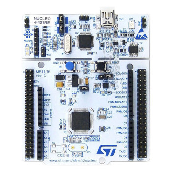
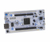
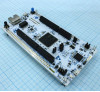
ST NUCLEO-H753ZI Stm32 Development Board
STM32H753ZI 480MHz Arm Cortex-M7 Cpu Fpu 2 MB Flash 1 MB SRAM ST-LINK V2 Debugger Programmer Arduino Ethernet
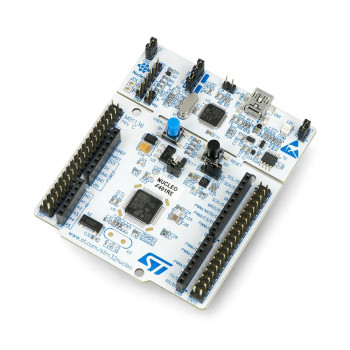
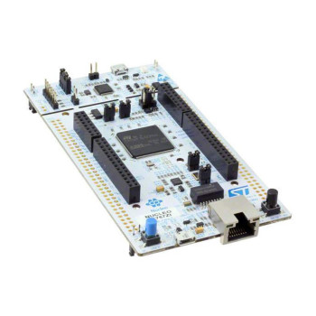
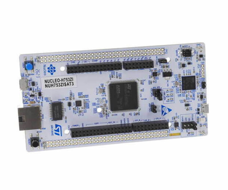
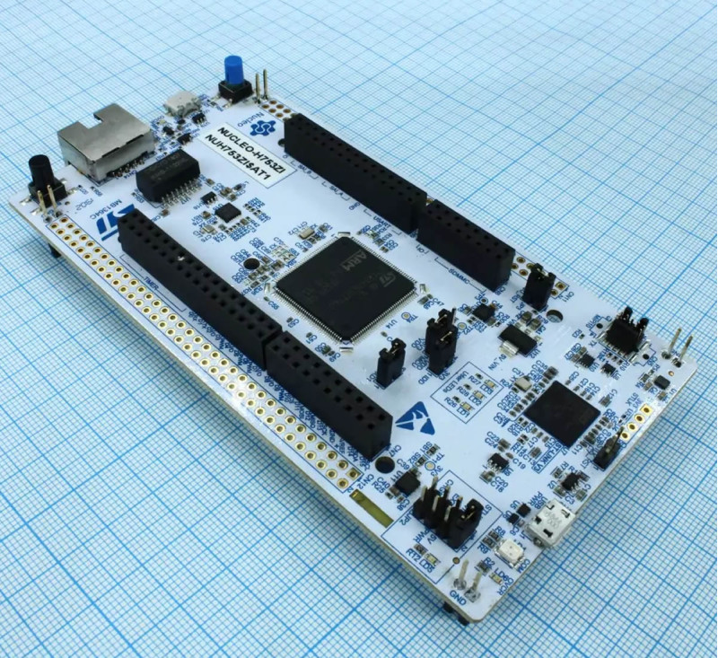
NUCLEO-H753ZI is the original STM32 Nucleo-144 development board from STMicroelectronics (MB1364). It carries the STM32H753ZI microcontroller in an LQFP144 package: Arm Cortex-M7 core with FPU, 480MHz clock, 2MB Flash and 1MB RAM. Unlike the H743, the H753 member of the STM32H7 family has a hardware cryptographic unit: AES 128/192/256, TDES, HASH (MD5, SHA-1, SHA-2) and HMAC accelerator, secure firmware upgrade support and secure access mode. The true random number generator (RNG) is present on both chips. This makes it suitable for trying out network devices that need encrypted communication and secure updates.
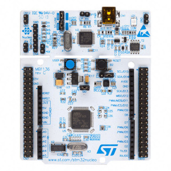
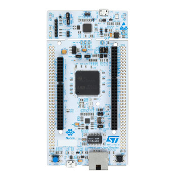
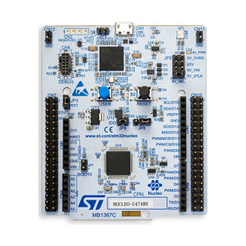
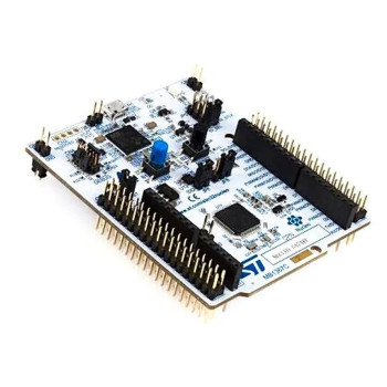
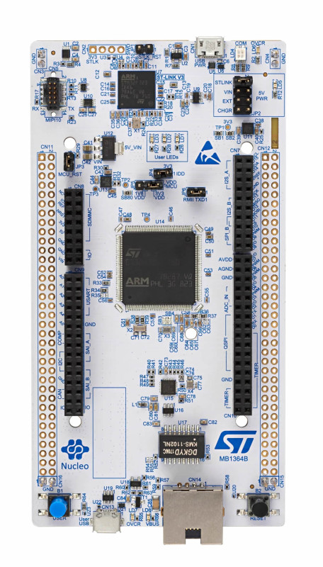
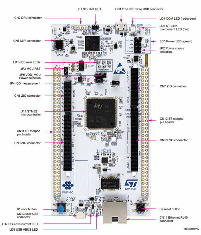
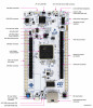
At the bottom edge of the board there is a 10/100 Ethernet connection with an RJ45 socket and a USB OTG Full Speed port with a Micro-AB connector; the board is ready for wired networking and USB device / host applications without an extra module. The STLINK-V3E programmer and debugger at the top needs no separate device: when connected to a computer with a Micro USB cable it appears as a virtual COM port, a USB drive for drag-and-drop programming and a debug port.
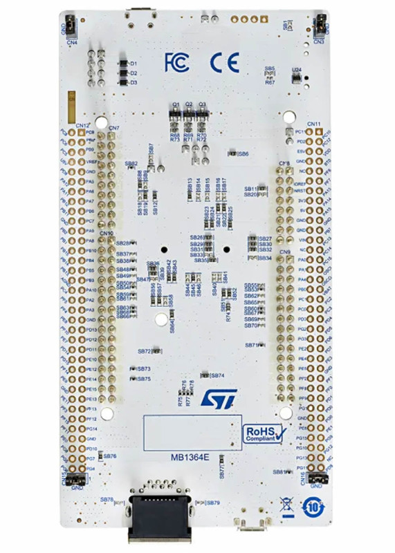
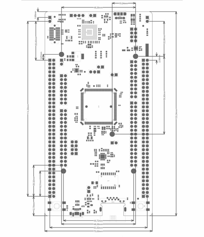
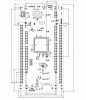
The ST Zio connector extends the Arduino Uno V3 layout; shields plug in directly. The ST morpho pin rows on both sides give access to all I/O pins of the microcontroller. The board can be powered from the STLINK USB, the VIN input, external 5V, a USB charger or 3.3V; the source is selected with the 5V PWR jumper (JP2). It is supported by STM32CubeIDE, Keil MDK, IAR EWARM and the STM32Cube HAL / LwIP examples.
Key features:
480MHz Cortex-M7: STM32H753ZI with FPU, Chrom-ART graphics accelerator and hardware JPEG codec; with 2MB Flash and 1MB RAM it handles compute-heavy work such as image, audio and signal processing.
Hardware cryptography: AES 128/192/256, TDES, HASH (MD5, SHA-1, SHA-2) and HMAC accelerator, secure firmware upgrade and secure access mode. This is what separates the H753 from the H743 on the same board; the true random number generator (RNG) is present on both.
Ethernet and USB on board: 10/100 Ethernet with RJ45 socket and Micro-AB USB OTG Full Speed; gateway, web server and USB device trials are done without an extra board.
STLINK-V3E: On-board programmer and debugger; virtual COM port, USB drive and debug port work over the same Micro USB cable.
Rich peripherals: 2 CAN FD, 6 SPI, 4 I2C, 4 USART + 4 UART, 4 SAI, Quad SPI, camera interface, LCD-TFT controller, 3 x 16-bit ADC and a 2-channel 12-bit DAC.
Features:
- Product type: STM32 Nucleo-144 development board (STMicroelectronics original, MB1364)
- Model: NUCLEO-H753ZI
- Microcontroller: STM32H753ZI, LQFP144 package, VDD 1.62V - 3.6V
- Core and speed: Arm Cortex-M7, FPU, up to 480MHz
- Memory: 2MB Flash, 1MB RAM
- Cryptography: AES 128/192/256, TDES, HASH (MD5, SHA-1, SHA-2), HMAC, true random number generator (RNG), secure firmware upgrade and secure access mode
- Graphics and imaging: Chrom-ART accelerator, hardware JPEG codec, LCD-TFT controller up to XGA resolution, camera interface
- Ethernet: IEEE 802.3 compliant 10/100 Ethernet MAC, RJ45 socket on board
- USB: 1 USB OTG Full Speed / High Speed, 1 USB OTG Full Speed; Micro-AB user USB connector on board
- Communication: 2 CAN FD, 6 SPI, 4 I2C, 3 I2S, 4 USART, 4 UART, 1 LPUART, 4 SAI, SPDIFRX, HDMI-CEC, dual-mode Quad SPI
- Analog: 3 x 16-bit ADC (up to 36 channels, 3.6MSPS), 2-channel 12-bit DAC
- Timers: 2.1ns high-resolution timer, 2 x 32-bit, 12 x 16-bit (2 advanced motor control + 10 general purpose) and 5 x 16-bit low-power timers; 4 DMA controllers
- GPIO: up to 114 GPIO with external interrupt capability
- Debugger: On-board STLINK-V3E (Micro USB); virtual COM port, USB drive (drag-and-drop programming), debug port
- Expansion: ST Zio connector (Arduino Uno V3 compatible) and ST morpho pin rows
- Power supply: STLINK USB VBUS, VIN 7V - 12V, external 5V, USB charger and external 3.3V; selected with the 5V PWR jumper (JP2: STLINK, VIN, EXT, CHGR)
- Indicators and buttons: 3 user LEDs, COM, 5V power and overcurrent LEDs; blue USER and black RESET button
- Clock source: 32.768kHz crystal (for RTC), 8MHz external clock (HSE)
- Software support: STM32CubeIDE, Keil MDK, IAR EWARM, STM32Cube HAL and examples, Zephyr
- Colour: White PCB, blue silkscreen
- Weight: about 65gr
Usage information:
- For first use leave the 5V PWR jumper (JP2) in the STLINK position and connect the board to the computer through the STLINK Micro USB port at the top. The 5V power LED and the COM LED light up; the board appears on the computer as a USB drive and a virtual COM port.
- Dragging a compiled .bin file onto the USB drive programs the board. For debugging select ST-LINK in STM32CubeIDE, Keil or IAR; the STLINK-V3E firmware is updated with STM32CubeProgrammer.
- For Ethernet plug a network cable into the RJ45 socket; with the LwIP examples in the STM32CubeH7 package the board is ready for ping, web server and TCP/UDP trials over the network. The Micro-AB USB port at the bottom (USB OTG Full Speed) is for USB device or host applications, not for programming.
- When USB power is not enough, move JP2 to the VIN position and apply 7V - 12V to the VIN pin, or in the EXT position apply 5V to the external 5V pin.
Application areas:
- Ethernet gateway, web server and Modbus TCP devices
- Encrypted communication with AES / SHA and secure firmware update trials
- Vehicle and machine control applications with CAN FD communication
- Motor control and high-resolution PWM (2.1ns timer) applications
- Image processing with the camera interface and JPEG codec
- Audio processing and digital audio applications with SAI / I2S
- User interfaces with LCD-TFT display and graphic panel prototypes
- IoT and remote monitoring devices
- Datalogger and precise analog measurement with 16-bit ADC
- Learning STM32H7 and Arm Cortex-M7 at university and in the lab
Precautions:
- No USB cable is included in the package. A USB-A / Micro-B cable is needed separately to connect the board to a computer.
- The I/O pins of the microcontroller are 3.3V level. Before connecting a sensor or module with 5V output directly to the pins, check in the datasheet whether the pin is 5V tolerant.
- Do not apply more than 12V to the VIN input. Move the JP2 jumper to the correct position before changing the power source; do not power the board from two sources at the same time.
- The pins used by Ethernet and USB are also present on the Zio / morpho connectors; check the pin table in the board user manual (UM2407) before using these pins for another purpose on a shield.
- Do not place the board on a conductive surface; the solder joints underneath may short. Hold the board by its edges against static electricity.
Package contents:
- 1 Piece NUCLEO-H753ZI Development Board
- Note: USB cable is not included in the package.