

- Stok Durumu: Stok Var
- Marka: OEM
- Model: DVB01 DC12V Modül
- SKU: RBZ.101.613
DVB01 DC12V Module
Voltmeter Charge Discharge Protection Voltage Range Comparator 220V 6A Relay Control Battery Lead Acid Lion Lithium Accumulator Protector Delay
Warnings:
- There is no reverse connection protection on the product supply input and the voltmeter input. If a reverse connection is made with high voltage, the product is permanently damaged.
- This product is a control device that can switch the power of the load on and off with a relay. It does not change the voltage. It is not a battery charging circuit.
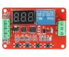
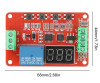
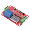
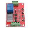
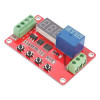
The DVB01 DC12V Module is an advanced relay control board that can perform 5 different tasks. It has selectable or adjustable functions depending on voltage and time. It can perform voltmeter charge discharge control and relay control operations between certain voltages. One of the 5 ready functions can be selected and used. It has the flexibility to change the functions according to your needs.
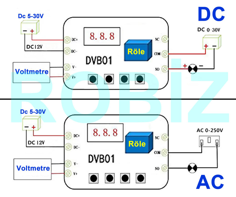
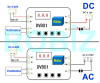
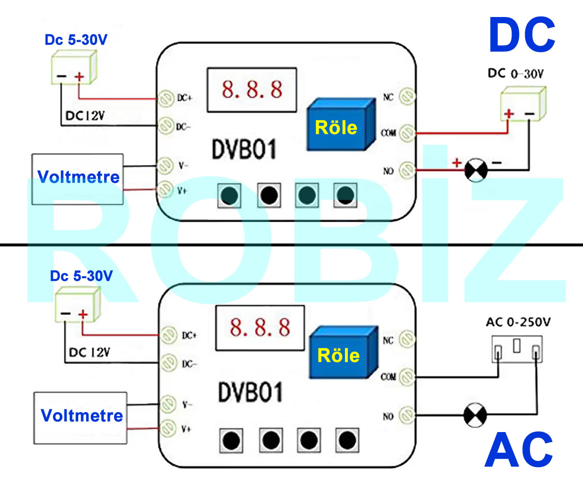
It requires an operating voltage between Dc 5V/30V. This supply must be provided from the DC+, DC- terminals. It can measure voltage between DC 0V/100V. Attention, voltage measurement and the supply of the device are different things. If you supply the device with 100V, the device will be damaged. The voltages of the system to be measured are connected to the circuit from the V+ and V- terminal inputs.
It has a relay that can operate at 220V 6A power in long term use. You can go up to 10A for short periods. It is recommended not to exceed 6A in long term use. If you go to higher currents, the switch inside the relay sticks from the heat and remains permanently short circuited. The control function cannot be performed. You may cause permanent damage to your target circuit.
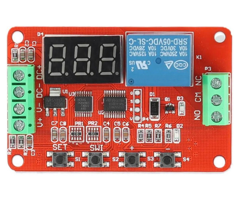
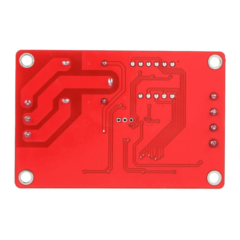
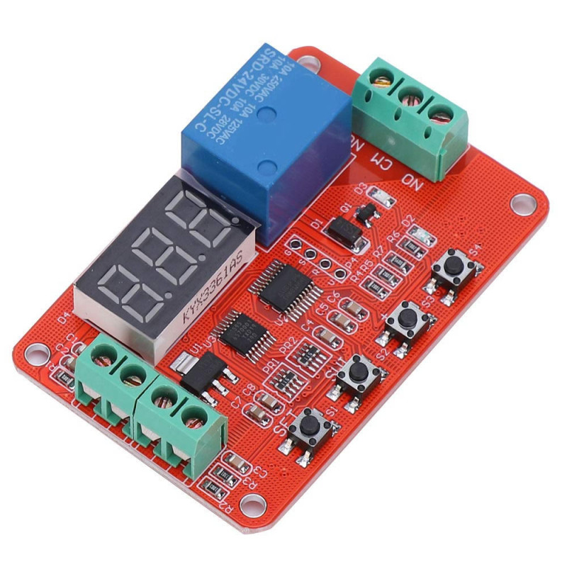
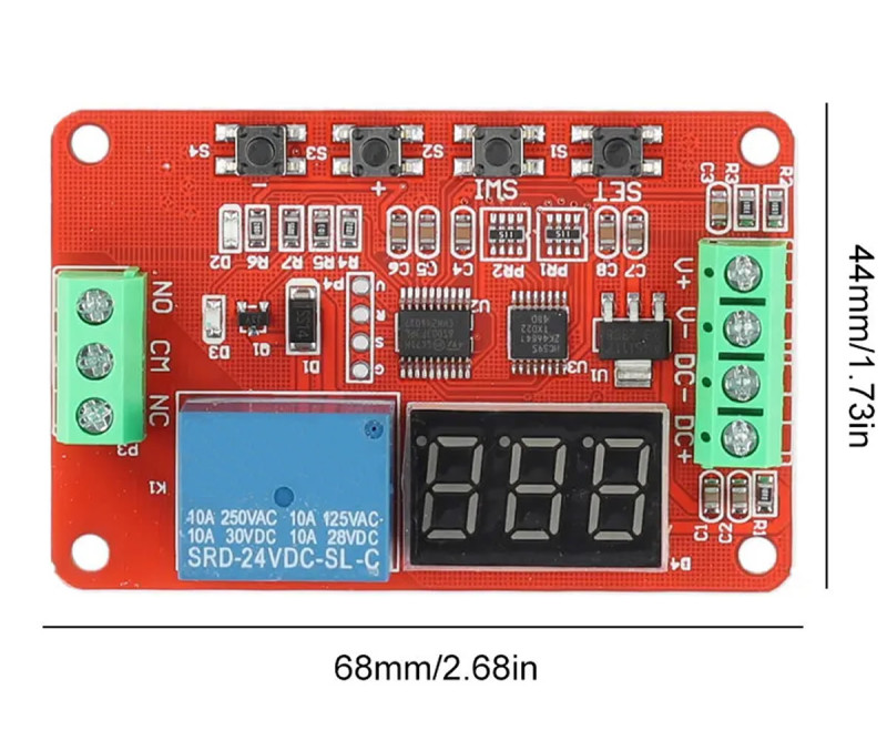
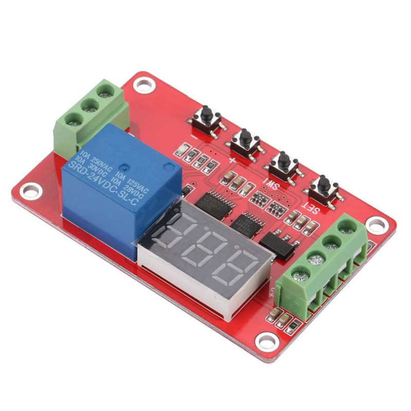
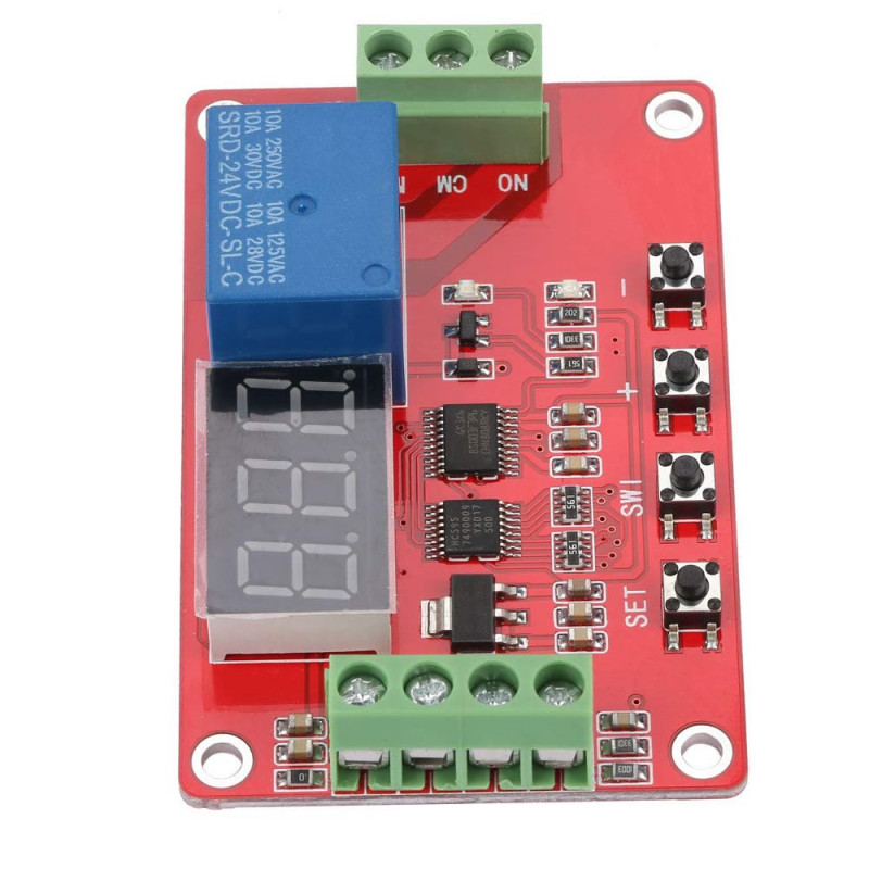
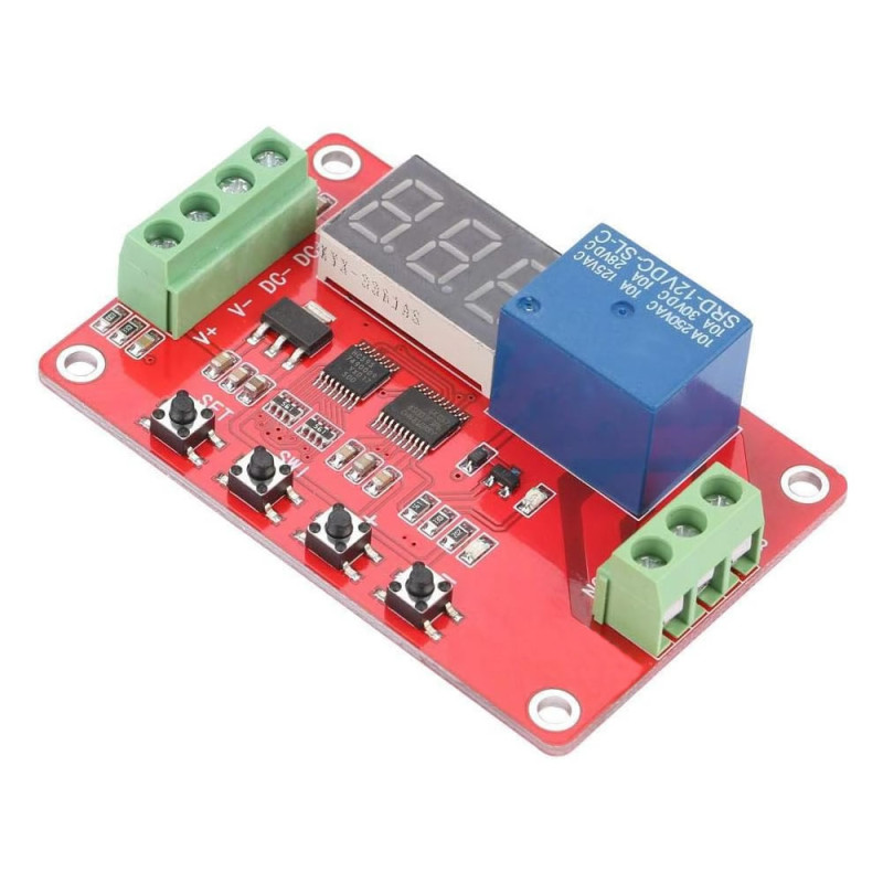
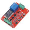
It has a 3 digit 7 segment display. It can be easily mounted with 4 mounting holes. It has four adjustment buttons. You can monitor the status with the supply and relay indicator leds.
Features:
- Model: DVB01 DC12V Module
- Operating voltage: DC 5V / 30V Battery
- Relay operating current: DC 30V 6A / AC 250V 6A ( Short term 10A )
- Voltmeter measuring voltage: 0V / 99.9V
- Accuracy: -+0.1V
- Time settings: 0-99 seconds (T1 and T2)
- 3 digit 7 segment display
- It saves the settings to memory. After a power outage, it continues to operate with the saved settings.
- T1 and T2 time variables adjustable between 0-99 seconds
- Extends battery life.
- Four adjustment buttons
- 3 way relay output terminal
- Relay status indicator led.
- Supply indicator led
- There is no reverse polarity protection! Make the DC input and V+/V- connections correctly.
- Color: Red
- Operating temperature: -20C / 60C
- 4 mounting holes
- Dimensions: 44mm x 68mm x 20mm
- Weight: 25gr
Buttons:
- Set: A short press turns off the screen. A long press opens the settings menu.
- SW1: Provides movement within the menu
- Plus: Provides upward navigation in the relevant menu.
- Minus: Provides downward navigation in the relevant menu.
Usage: A short press on Set turns on the screen. A long press on Set allows entering the parameter menu. Parameter settings from P0 to P6 can be made. The parameter setting menu is opened with a long press on Set. The parameter number is changed with the plus minus buttons and the Set key is long pressed for the relevant parameter setting.
P0: Allows the operating function of the product to be selected. The product can perform 5 functions. The functions are explained in the descriptions below. The Set button is long pressed. While P0 is selected in the settings menu, the set key is pressed. The function number is changed and it is returned by pressing the set key briefly. The device continues to operate in the determined function. If there is a voltage or time setting need that may be required in the relevant function, you will need to make these settings from the other parameter menus as well.
P1: It is the voltage variable setting number 1.
P2: It is the voltage variable setting number 2.
P3: It is the voltmeter calibration menu. If you think there is an error in the measured voltage, you can improve the voltage measurement of the device by setting the voltage that should be from here.
P4: It is the 1st time variable setting menu. You can examine the effects of these variables by setting short periods. Do not make time settings in this menu unless necessary.
P5: It is the 2nd time variable setting menu. You can examine the effects of these variables by setting short periods. Do not make time settings in this menu unless necessary.
Functions: The selection of the operating modes of the device is under the P0 menu. The device will operate according to the program number you select in this menu. The descriptions of the functions are below. The settings menu is entered with a long press on Set. While at P0, the function selection menu is entered by pressing the set key. It is exited by bringing it to the function you want and pressing the set keys briefly.
F01 Voltmeter: It shows the voltage at the V+ V- inputs. There is no control function on the relay.
F02 Charge control: If the battery voltage exceeds the set upper limit, it cuts off the charge.
Overcharging and heating of some batteries damages the battery. With this module you can prevent your battery from being overcharged. This circuit is not a charging circuit. It only monitors the charge. In case of overcharge, it cuts the connection between the battery and the charging circuit via the relay. The greater of the v1 and v2 values set in the system will be used as the cut off voltage of the charge. The device automatically uses the higher voltage value. For this reason, you must check that both of the voltages you set here are correct. The smaller voltage becomes the starting value of the charge. The relay remains active until the higher voltage setting is reached. When the upper charge voltage is reached, the relay turns off.
F03 Discharge Control: If the battery voltage falls below the lower limit, it disables the load.
Overdischarging of accumulators causes permanent physical capacity loss to the battery. The voltage of the batteries drops very suddenly. For this reason, after a certain level it is not desired that the battery supplies the load anymore. In this function, when it goes below the voltage you will determine, the relay connection between the battery and the load is turned off. And your battery is prevented from being completely depleted. The smaller of the v1 and v2 values set in the system will be used as the cut off voltage of the discharge. The device automatically uses the lower voltage value. For this reason, you must check that both of the voltages you set here are correct. A battery that has been discharged and whose load connection is cut by the relay can be charged. During this charging the relay does not become active but the voltage of the battery is monitored. The relay will remain off until the higher voltage value you set is reached. When it is charged to the upper voltage level, the module activates the load output via the relay.
F04 Relay Control Within Voltage Range: The relay is active only in the determined V1-V2 range.
The relay supplies power to the load between the set V1 and V2 voltages. When it goes outside this range, the relay turns off and the operation of the load is prevented. The device itself knows which is the high and the low voltage. You do not have to set the high voltage or the low voltage specifically to one or the other.
F05 Relay Control Outside Voltage Range: The relay is active OUTSIDE the V1-V2 range.
The relay supplies power to the load outside the set V1 and V2 voltages. Within this range the relay turns off and the operation of the load is prevented. The device itself knows which is the high and the low voltage. You do not have to set the high voltage or the low voltage specifically to one of them.
Description of the input terminals:
- 1, DC+: Positive supply input of the board DC 5V / 30V
- 2, DC-: Ground supply input of the board DC 5V / 30V
- 3, V+: Voltmeter positive input
- 4, V-: Voltmeter negative input
Description of the output terminals:
- NO: It is the normally open pin of the relay. When the relay is activated, there is a connection between COM and NO.
- COM: Relay common pin
- NC: It is the normally closed pin of the relay. Before the relay is activated, there is a connection between COM and NC.
Package contents:
- 1 Piece DVB01 DC12V Module
.