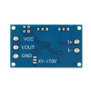
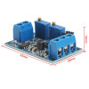
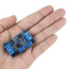
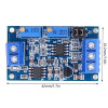
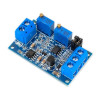
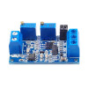
- Stok Durumu: Stok Var
- Marka: OEM
- Model: 4-20mA Akım to Voltaj Çevirici
- SKU: RBZ.100.481
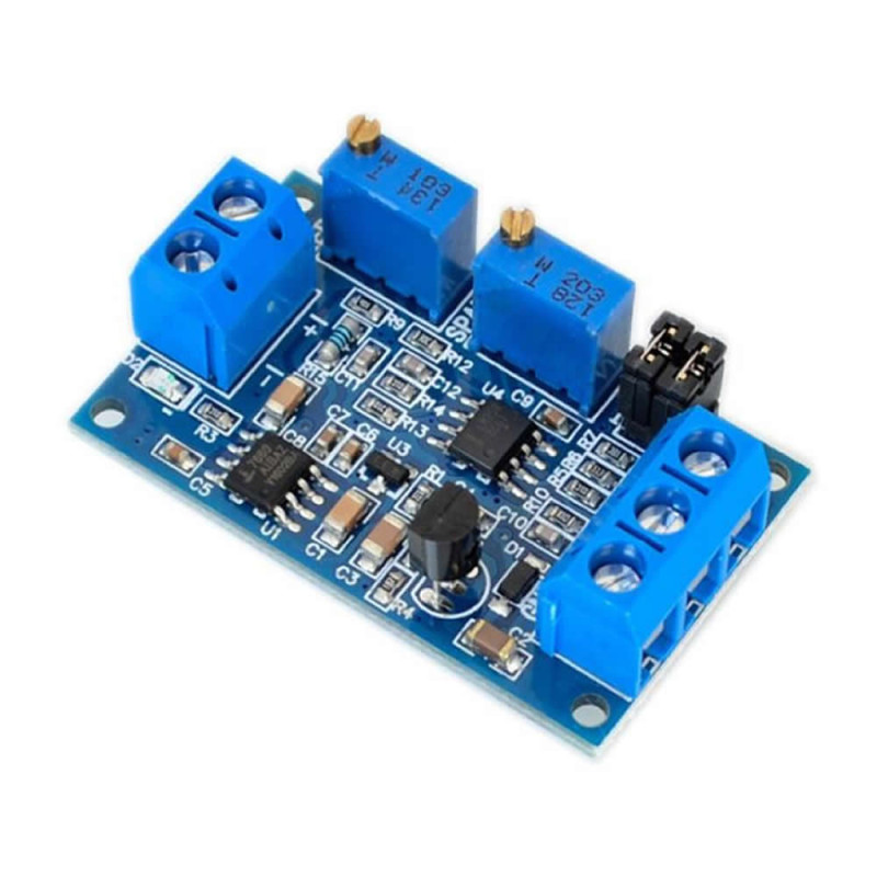
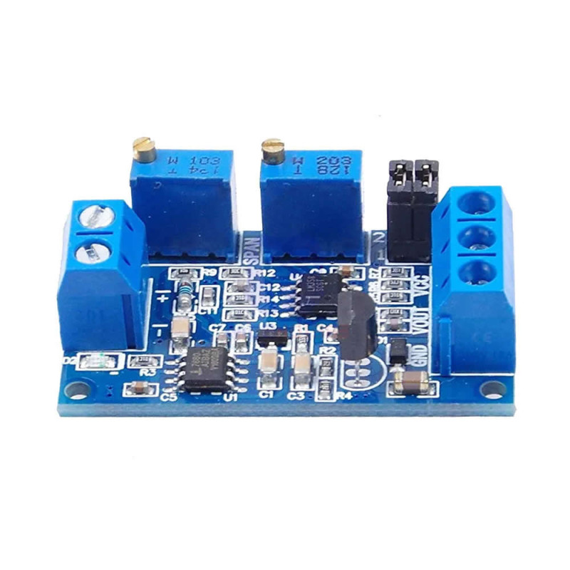
4-20ma Current Voltage Signal Converter Module
0 -20mA 0-3.3V 0-5V 0-10V Sensor Industrial Automation Plc Temperature Pressure Flow Water Level R&D Test Calibration
It is a module that converts a 4-20 mA current signal into a 0-10 V voltage signal. It allows current signals coming from industrial sensors and transmitters to be converted into voltage values that devices such as microcontrollers or PLCs can read. Voltage signals may weaken as distance increases. However, current signals suffer less loss over long distances. This module converts current signals carried over long distances into a voltage signal in the 0-10V, 0-5V or 0-3.3V range, making it possible to transfer them reliably to receiving devices.
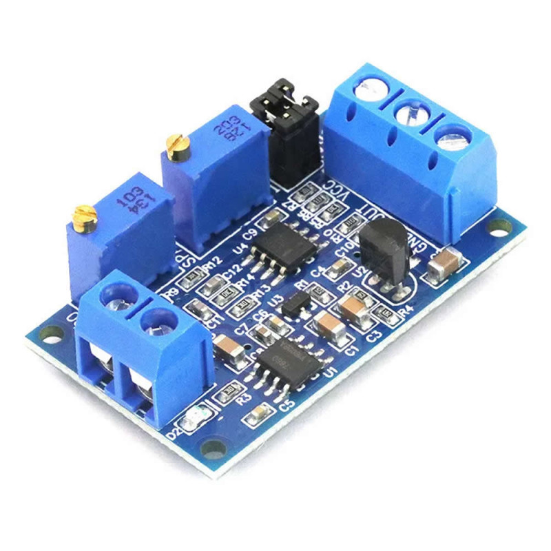
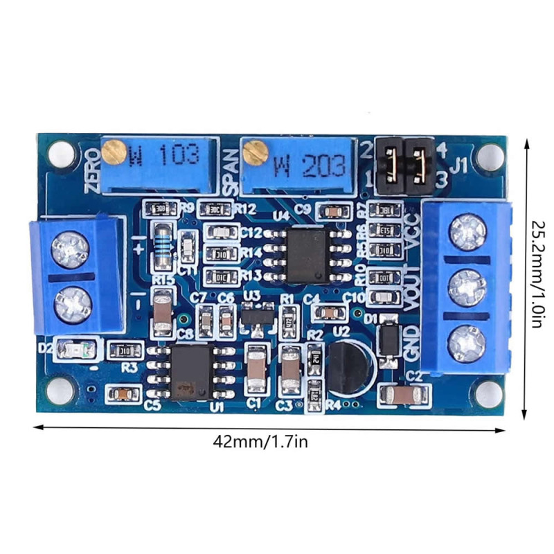
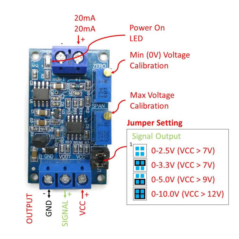
Thanks to the jumper settings on the board, the desired output voltage range can be selected. Using the ZERO and SPAN potentiometers, accurate scaling (calibration) can be performed between the input current signal and the output voltage. This provides a flexible solution for different sensor types and applications.
Features:
- Board supply voltage: DC 7V / 36V ( supply must be 12V for 0-10 V output )
- Output signal ranges: DC 0-3.3V / 0-5V / 0-10V
- 2 jumpers for output voltage selection
- Input current range: 0-20 mA or 4-20 mA
- Calibration: Dual trim pot for zero and span adjustment
- Reverse supply connection protection
- Input impedance: 100ohm internal resistance ( 2V drop at 20 mA )
- Supply indicator led.
- Operating temperature: -20C / 60C
- Color: Blue
- 4 mounting holes
- Input and output terminal blocks.
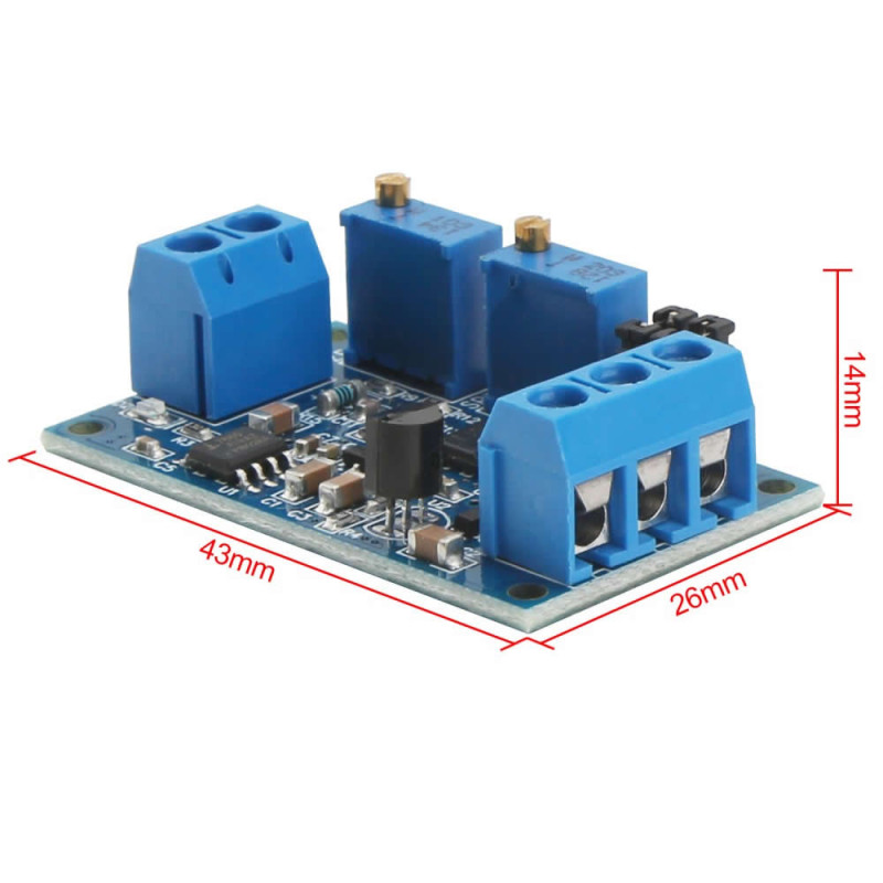
- Dimensions: 26mm x 43mm x 14mm
- Weight: 10gr
Areas of Use:
- Industrial automation and measurement: It allows 4-20mA sensors to be used with devices that only have voltage inputs in PLCs or data acquisition systems. For example, the 4-20mA output of a pressure or level transducer can be connected to a PLC with a 0-10 V input via this module.
- IoT and microcontroller projects: It is used for integrating industrial sensors on platforms such as Arduino and Raspberry Pi. Remote sensors with 4-20mA output can be converted to the 0-5V or 0-3.3V range through the module and read on the ADC (analog-digital converter) inputs of these platforms.
- Remote monitoring and data transmission: A current loop is used to prevent measurement signals from weakening over long cable distances, and at the receiving end it is converted into a voltage signal with this module.
- It plays a role in safely transmitting 4-20mA sensor data such as water level, temperature and pressure to central monitoring stations or control rooms as a voltage signal.
- R&D and calibration applications: It can also be used for simulating and calibrating sensor signals in laboratory environments. Thanks to the adjustable output ranges, a signal sourced from 4-20mA can be obtained in the desired voltage range for test purposes.
Connection and calibration:
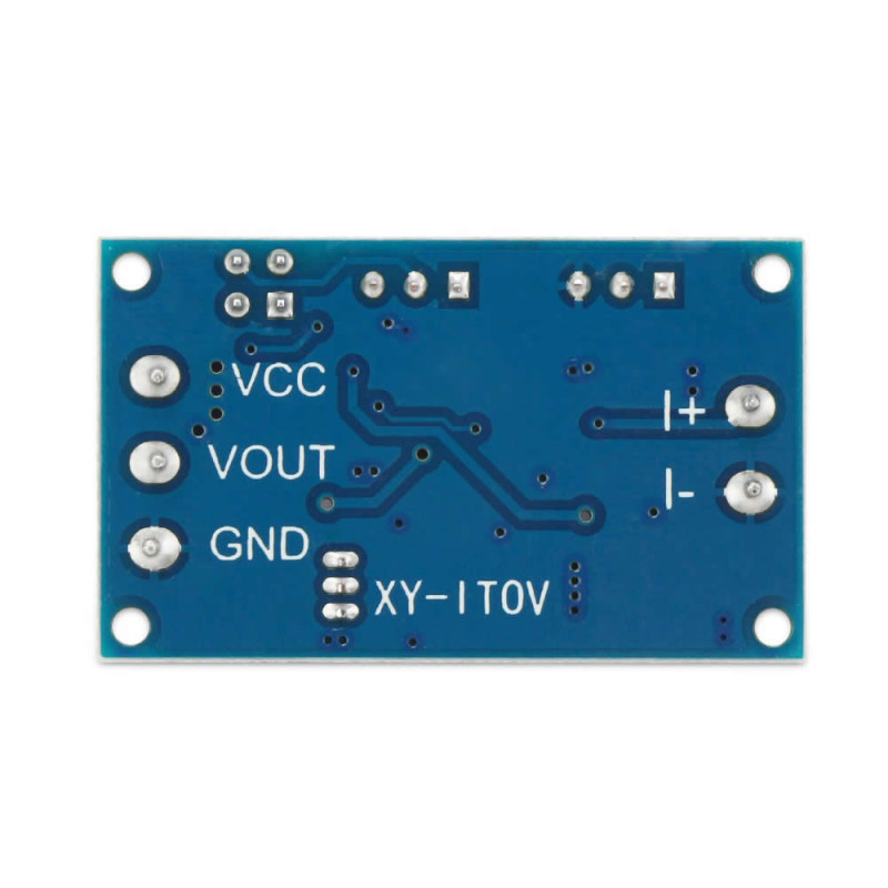
Power and input connections: Connect the VCC and GND pins of the module to a stable power supply in the DC 7/36V range (if 0-10V output will be taken, a supply of approximately 12V and above is recommended). Connect the current signal input to the I+ and I- terminals on the module. Typically, the positive line of the 4-20mA signal coming from the sensor is connected to the I+ terminal, and the return line of the sensor (usually ground) is connected to the I- terminal. The VOUT output of the module is the voltage signal to be read; connect this terminal to the analog input of the microcontroller or to a measuring device (voltmeter). Make sure all devices use a common ground reference (the grounds of the module, sensor and reader device must be the same).
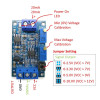
Output range selection with jumpers: Set the jumper configuration on the board to determine the desired output voltage range. By fitting the jumper caps to the appropriate pins, you can select the 0-3.3V, 0-5 V or 0-10V output mode.
- ON: jumper fitted
- OFF: jumper not fitted.
- 4 -20mA:
- 0 -2.5V: pin 1, 2 ON pin 3, 4 ON
- 0 -3.3V: pin 1, 2 OFF pin 3, 4 OFF
- 0 -5.0V: pin 1, 2 ON pin 3, 4 ON
- 0 -10.0V: pin 1, 2 ON pin 3, 4 OFF
- 0 -20mA:
- 0 -3.3V: pin 1, 2 ON pin 3, 4 ON
- 0 -5.0V: pin 1, 2 ON pin 3, 4 ON
- 0 -10.0V: pin 1, 2 ON pin 3, 4 OFF

Calibration preparation: For precise calibration, before powering the module, turn the ZERO and SPAN potentiometers fully to the left position (counter-clockwise all the way). This operation brings the potentiometers to the starting point and lets you adjust more easily. Then power the module; if the connection is correct, the D2 LED will light up.
Zero point adjustment (ZERO): Set the input current to the minimum value. If your sensor is of the 4-20mA type, apply 4mA current (apply 0mA for 0-20mA input). Under this condition, measure the output of the module and start adjusting the ZERO potentiometer. Slowly turn the ZERO pot clockwise to bring the VOUT output to the desired minimum voltage. For example, if you want a 4 mA input to give a 0.00V output, make the ZERO adjustment so that the output voltage is 0V. (On 4-20 mA sensors, setting a 0V output for a 4mA input is not recommended; in that case it becomes harder for the system to detect a possible sensor cable break. If desired, by setting an offset voltage of a few volts for a 4 mA input, the output can be made to drop to 0V in the 0mA (current interruption) condition.)
Full scale adjustment (SPAN): Raise the input current to the maximum value (20mA, which is the sensor's full measurement current, must be applied). Measure the VOUT voltage, turn the SPAN potentiometer clockwise and set the output to the maximum value of the range you selected. For example, if you are working in 0-10V mode, ensure that the output is 10.00V for a 20mA input. Similarly, in the 0-5V range, SPAN is adjusted so that a 5.00V output is obtained for 20mA. You can observe that the output voltage increases as you turn the SPAN pot clockwise and decreases as you turn it counter-clockwise.
Verification: After the calibration process is complete, test the module output by varying the input current between the min-max values. Verify that you get the minimum output voltage you set with 4mA (or 0mA), and the maximum output voltage with 20mA. A linear change should also be observed at intermediate values (the module gives a linear output). If necessary, make small corrections on the ZERO and SPAN potentiometers to achieve the desired precision. When calibration is complete, the module will output the current signal at the input as correctly scaled voltage in accordance with your jumper selection.
Package contents:
- 1 Piece 4-20ma to Voltage Converter Module