- Stok Durumu: Stok Var
- Marka: STMicroelectronics
- SKU: RBZ.200.048
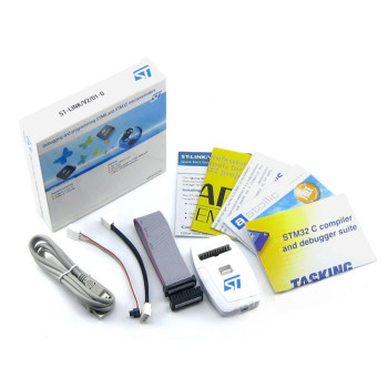
ST STLINK-V3 modular in-circuit debugger and programmer for STM8 and STM32
SWD JTAG SWIM VCP STM32CubeIDE STM32CubeProgrammer Bridge SPI I2C CAN Motor IoT Production
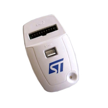
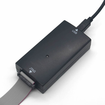
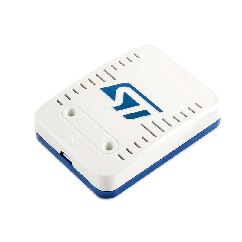
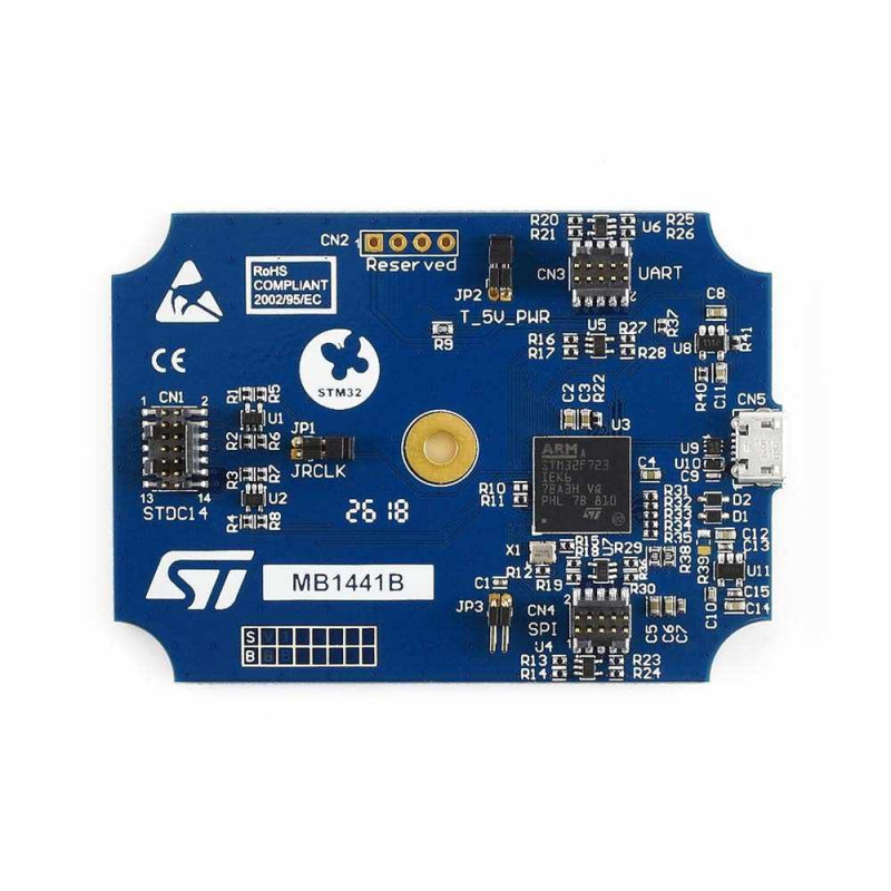
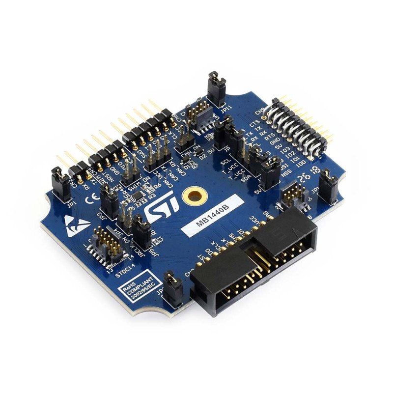
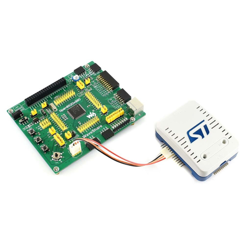
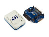
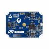
The STLINK-V3SET is a modular, stand-alone debugging and programming probe developed by STMicroelectronics for the STM8 and STM32 microcontrollers. It is composed of a main module (MB1441) and a complementary adapter board (MB1440). The SWIM and JTAG/SWD interfaces are used to communicate with any STM8 or STM32 microcontroller located on an application board. It is an original ST product.
The STLINK-V3SET also provides a Virtual COM port (VCP) interface allowing the host PC to communicate with the target microcontroller through a UART, and bridge interfaces (SPI, I2C, CAN, UART, GPIO) allowing, for example, programming of the target through its bootloader. A second Virtual COM port can also be used with the bridge UART signals including optional RTS and CTS; these signals are available on the adapter board (MB1440) only. The second Virtual COM port is enabled by a reversible firmware update that disables the mass storage interface used for drag-and-drop Flash programming.
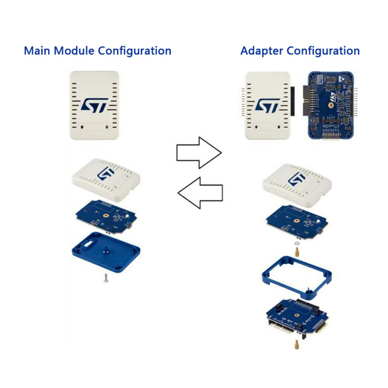
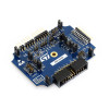
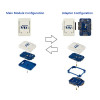
All functions are designed for high performance: all signals are 3.3V compatible except the SWIM protocol, which supports the 1.65V - 5.5V range. For high performance the main module contains only the MB1441 board; for additional functions the adapter configuration uses the MB1441 and MB1440 boards together. Its modular architecture allows the main features to be extended with additional modules. Product presentation and support page: https://www.st.com/en/development-tools/stlink-v3set.html
Features:
- Product type: Modular, stand-alone debugging and programming probe for STM32 and STM8 (original STMicroelectronics)
- Model: STLINK-V3SET (main module MB1441 + adapter board MB1440)
- Debug interfaces: JTAG, SWD and SWV (serial wire viewer trace output), SWIM (STM8, with MB1440 adapter board only)
- SWD speed: Up to 24MHz (with SWV trace support)
- JTAG speed: Up to 21MHz; JTAG daisy chaining is not supported
- JTAG / SWD application voltage: 3V - 3.6V, 5V tolerant inputs (extended down to 1.65V with the separately sold B-STLINK-VOLT or B-STLINK-ISOL board)
- SWIM: 1.65V - 5.5V application voltage, low speed and high speed modes, 2.54mm pitch SWIM header
- Virtual COM port (VCP): 732bps - 16Mbps, 3V - 3.6V, 5V tolerant inputs; available on the STDC14 connector (not on MIPI10)
- Multi-path bridge: USB to SPI / UART / I2C / CAN / GPIO bridge, 4 GPIOs; signals on the adapter board (MB1440) only
- Bridge I2C: Optional 680ohm pull-up resistors enabled with the JP10 jumpers; in that case the target voltage (T_VCC) must be supplied to MB1440
- Second Virtual COM port: Bridge UART with RTS / CTS hardware flow control (with dedicated firmware)
- Drag-and-drop programming: Drag-and-drop Flash programming of binary (bin) files
- USB: USB 2.0 High Speed compatible interface, Micro-B connector; the probe is powered from USB
- Firmware: Direct firmware update support (DFU)
- Debug cables: STDC14 to MIPI10 / STDC14 / MIPI20 flat cables (1.27mm pitch connectors)
- LED: Two-color LEDs: communication and power
- Software support: STM32CubeIDE, STM32CubeProgrammer, Keil MDK-ARM, IAR EWARM, SW4STM32 (GCC); STVP and STVD for STM8
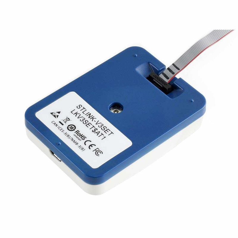
- Material and color: White - blue plastic cased main module, blue adapter board
Usage information:
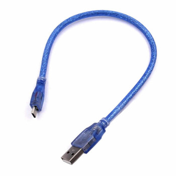
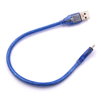
- Connect the programmer to the PC with a micro USB cable (the cable is not included in the package). The probe is recognized once STM32CubeProgrammer or STM32CubeIDE is installed; use the firmware upgrade tool in STM32CubeProgrammer to keep the firmware up to date.
- SWD and SWV: the debug / programming protocol for STM32; the signals are 3.3V compatible. This function is available on MB1441.CN1 and MB1440.CN1, CN2, CN6. JTAG: available on MB1441.CN1 and MB1440.CN1, CN2.
- SWIM (STM8): to enable the SWIM protocol, JP4 and JP6 on the MB1440 board must be in the ON position. The signals are on the MB1440.CN4 connector.
- Virtual COM port: used directly as a Virtual COM port of the PC, connected to the USB connector CN5; available on MB1441.CN1 and MB1440.CN1, CN3. The T_VCP_RX (RX) signal is RX for the target, the T_VCP_TX (TX) signal is TX for the target.
- Bridge functions: the SPI signals are on MB1440.CN9 and CN8, the I2C and UART signals on MB1440.CN9 and CN7, the CAN logic signals (Rx/Tx) on MB1440.CN9. All bridge signals can be accessed easily on CN9 with wire clips.
Application areas:
- Motor control and driver boards: STM32 software development
- Automation and industrial control devices: debugging
- IoT and wireless sensor devices (STM32WB / STM32WL) programming
- Education: STM32 and STM8 embedded systems courses and laboratories
- Production line Flash programming and loading through the bootloader
- Programming and repair of legacy STM8 based products with SWIM
- Testing CAN, I2C and SPI buses from the PC (bridge interface)
- Real-time software performance analysis with SWV trace output
- First bring-up work on R&D and prototype boards
Precautions:
- No micro USB connection cable comes with the product; you must obtain it separately.
- The probe does not power the target board. The JTAG / SWD and VCP signals are for 3V - 3.6V targets; do not use the interfaces other than SWIM on targets outside this range.
- The SWIM, bridge (SPI / I2C / CAN / UART / GPIO) and second Virtual COM port signals are available on the MB1440 adapter board only.
- The firmware that enables the second Virtual COM port disables the mass storage interface used for drag-and-drop programming; the operation is reversible.
- To connect CAN target signals directly to MB1440.CN5, the JP7 jumper must be fitted (closed, CAN ON) and the CAN voltage must be supplied to CN5.CAN_VCC.
- The legacy 20-pin Arm JTAG connector (CN2) on MB1440 has the same pinout as ST-LINK/V2, but the JTAG TRST signal (pin 3) is not managed; JTAG daisy chaining is not supported.
- At high SPI / UART speeds use a flat ribbon cable (MB1440.CN8 / CN7) with the unused signals grounded on the target side instead of wire clips; long and unshielded wires reduce signal quality.
Package contents:
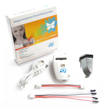
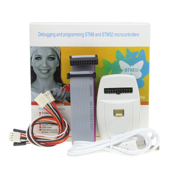
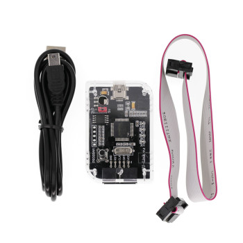
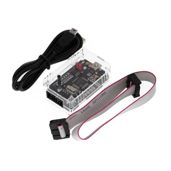
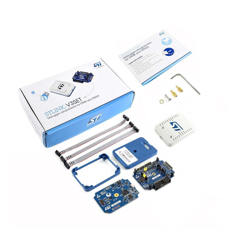
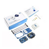
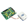
- 1 Piece STLINK-V3SET Programmer with Plastic Case
- 1 Piece MB1440B Adapter Board
- 1 Piece Plastic Protection Part
- 2 Pieces Spacer
- 1 Piece Allen Key
- 1 Piece 1.27mm 2x5 Pin Cable
- 1 Piece 1.27mm 2x7 Pin Cable
- 1 Piece 1.27mm 2x10 Pin Cable
- Note: Micro USB cable is not included in the package.