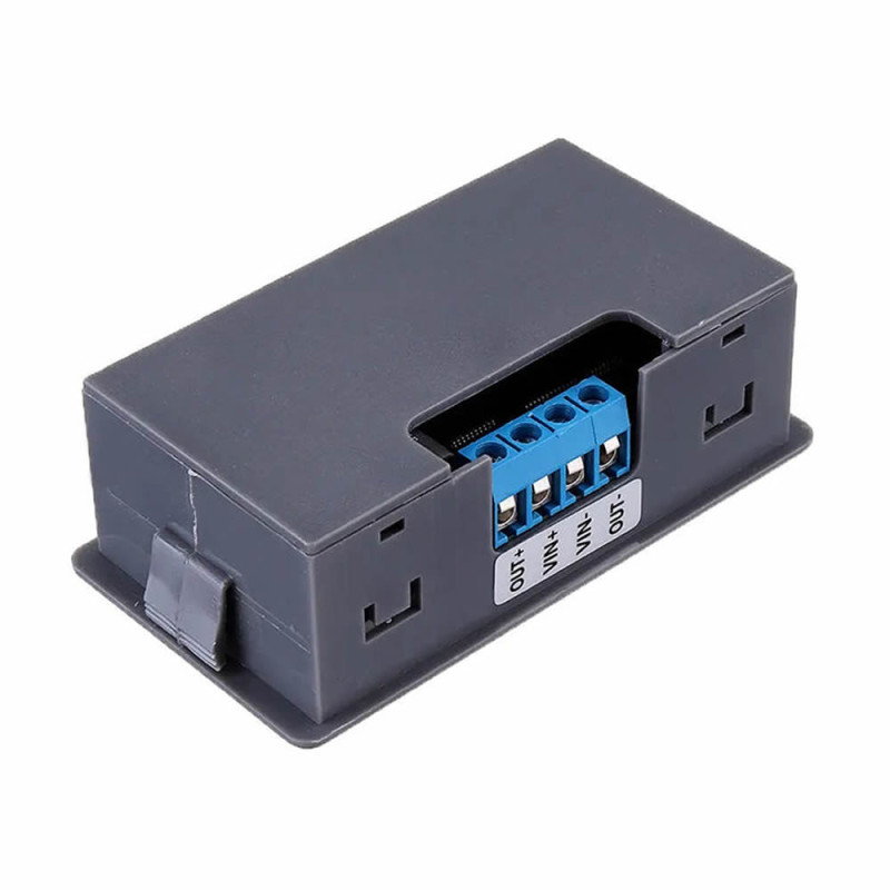
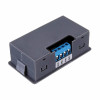

- Stok Durumu: Stok Var
- Marka: OEM
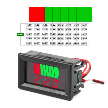
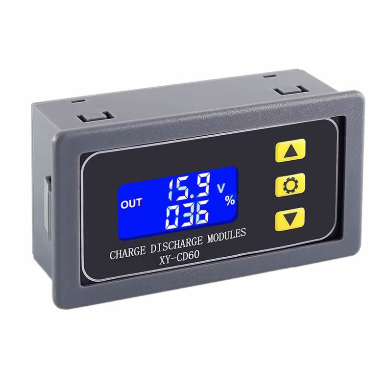
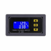
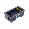
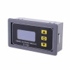
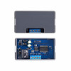
- Model: XY-CD60 Şarj Deşarj Kontrol Modülü
- SKU: RBZ.101.139
XY-CD60 Battery Over Charge Discharge Control Module
Lithium Lipo Battery Lead Acid Accumulator Protector DC 6-60V Panel Type Box Over Discharge Over Charge Protection Circuit
The product basically has 2 functions. It controls the battery charge and discharge processes. It prevents your battery from being damaged without you noticing.
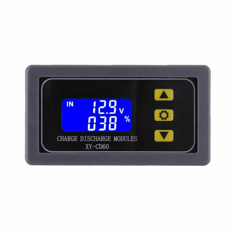
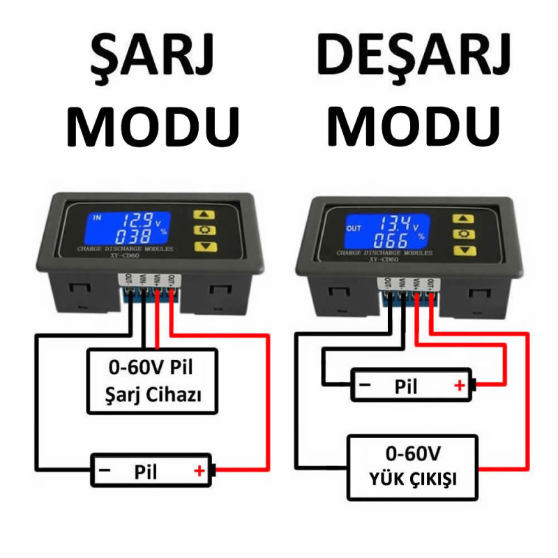
Charge Mode P-1: It controls the charging of the accumulator connected to the device. The IN text on the lcd shows that you are in charge mode.
Lower and upper values are entered for charging. If the voltage level of the battery to be charged is lower than this upper value, it opens the relay and the accumulator starts to be charged with the voltage coming from the input supply. When the accumulator voltage exceeds the upper value, it ends the charging by closing the connection of the input supply in order to protect the accumulator.
You need to know the charge upper value of this battery. You need to learn the voltage values at which charging should be cut off according to the condition of your battery from the manufacturer or the seller. The percentage display ratio of the battery voltage is determined according to the lower and upper values you enter.
Calculation formula: V/(UP-DOWN).
Discharge Mode P-2: It controls the use of the accumulator connected to the device with a load. The OUT text on the lcd shows that you are in discharge mode.
The situation of using your battery by driving a lamp, motor etc. is called battery discharge. During the discharge process of batteries, when their capacity begins to decrease, their voltage drops very quickly. While this decrease occurs very quickly, physical deteriorations also occur in the battery. For this reason, for example, it is essential that you do not consume a battery that you use down to the 10-20% levels all the way to 0%. The situation of batteries running out without users being aware of it is frequently encountered, for example; car accumulators going flat. Although this situation comes up frequently, preventing it is very necessary for the service life of the accumulator.
After this explanation, let us explain the use of this product in the discharge process. In the device settings you need to specify a lower limit for discharge. While above this limit, the board allows the battery to drive the load. When it falls below this limit, it prevents the battery from being completely emptied by closing its relay so that the battery is not damaged. During the discharge process you can monitor the status with the indicator led.
WARNING: This board provides automatic control of the charge and discharge processes of the battery. You must not forget that a current controlled battery charge board must also be connected to this device in order to charge the battery. The battery charging process should not be done directly with an adapter. This board only provides a rougher charge control by monitoring the battery voltage. Real charge control should be done by devices in which battery charge currents can be monitored. However, users generally tend to charge batteries simply with adapters. Even if users are going to use an adapter, if they use this type of board they will be protected from critical battery damage situations.
Usage:
UP:
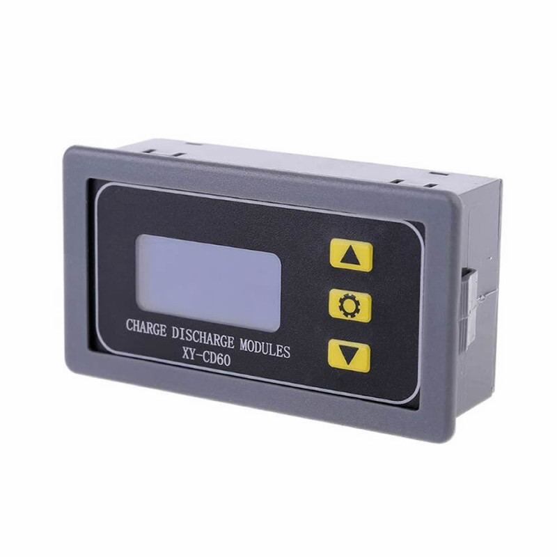
1- Pressing the Up key briefly shows the usage information of the battery as % and time.
2- Pressing the Up key longer than 5 seconds allows changing the product between charge and discharge modes. IN is charge mode. OUT is discharge mode.
SET:
1- Pressing the Set key briefly shows the parameters in the current mode ( Lower and upper values ).
2- Pressing the Set key long allows you to change these parameters. You make the relevant settings according to the charge or discharge mode.
DOWN:
1- Pressing the Down key briefly turns the relay on and off. ( It is used in danger situations.)
2- Pressing the Down key long adjusts the lcd backlight.
After all settings are made, the settings are saved and the setting menu is exited by long pressing the SET key. If you want to make a setting again, you will need to enter the setting menu by long pressing again.
Warnings:
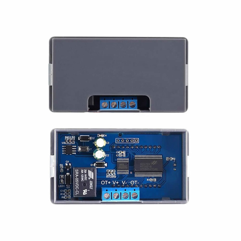
- There is a 10A relay in the device. However, continuous high current charging or load driving may cause the relay contacts to stick. For this reason you should not operate it above 5A for a long time.
- This device does not perform voltage conversion. Do not assume that if you connect a 48V supply, the voltage will be lowered by the device to charge a 12v battery. This device only performs relay switching. It enables the battery charge or the load to be driven within the limits you have determined.
- After the settings are made and exited, if the low voltage limit is higher than the high voltage limit, the device displays ERR and reports that there is an error in the settings. You need to correct the settings.
- On the product you can also have time based operations performed. Operations that will vary between 0-999 seconds can be performed. For example, a setting such as let it drive the load ten seconds after the product is turned on can be made…
Features:
- Model: XY-CD60
- Operating voltage: DC 6V / 60V ( Battery voltage can be maximum 48V )
- Operating current: 5A
- Battery charge control mode ( It follows the battery charge only according to voltage levels. You also need to have a battery charge product. )
- Battery discharge control
- Dual operating mode
- High resolution large lcd indicator screen
- 3 Menu setting buttons
- Over charge protection
- Over discharge protection
- Charge and discharge time setting support
- Automatic detection parameters
- Power saving mode support
- Automatic battery detection
- It can display the accumulator voltage as a percentage and operating time
- Charge time setting: 00:00 -99:59 hours
- Discharge time setting: 00:00 -99:59 hours
- Delay: 0 -999 seconds
- Operating temperature: -10C / +80C
- Color: Gray / Black
- Panel type plastic box
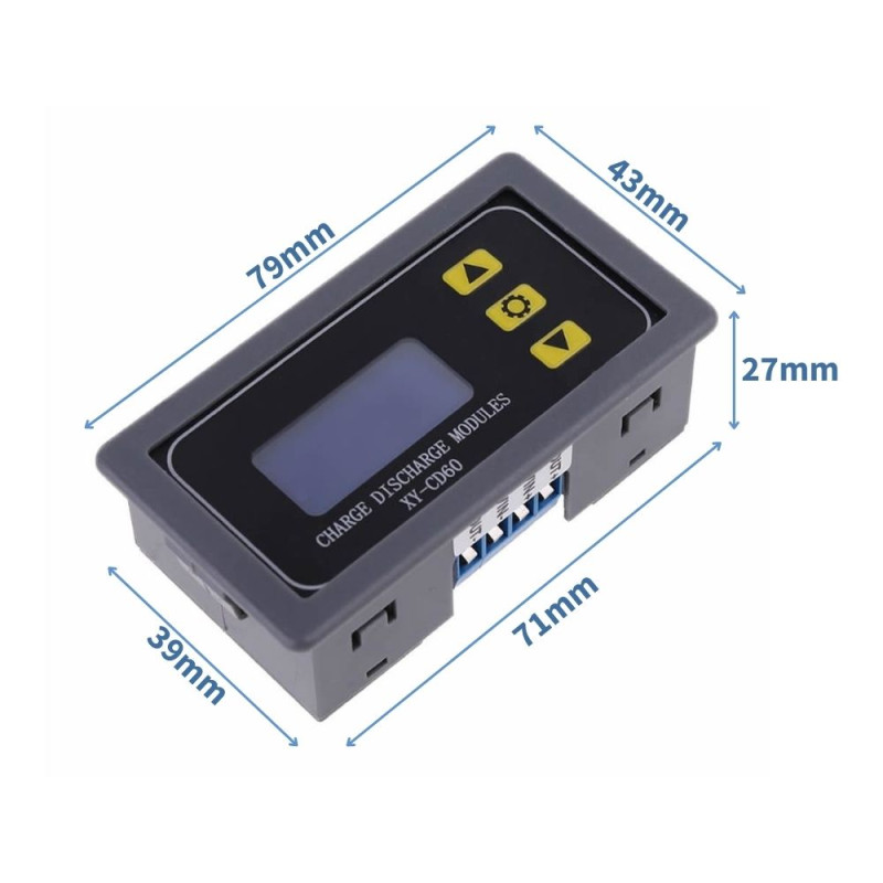
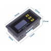
- Dimensions: 27mm x 43mm x 79mm
- Weight: 45gr
Package contents:
- 1 Piece XY-CD60 Charge Discharge Control Module
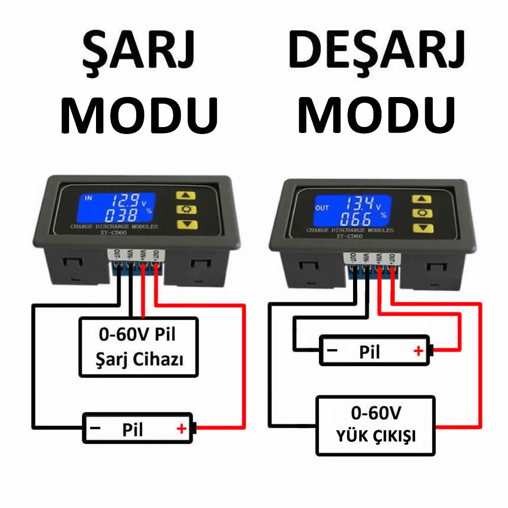
[Charging Control P-1 Mode]
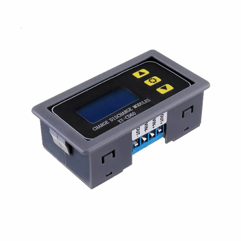
Input terminal connect DC 6V-60V charger which use for battery.
Output terminal connect 1pc of DC 6 -60V battery. It will display 0.00V and nbE if the battery does not meet the requirements.
Output turn ON and the input charger starts charging the battery if battery voltage is less than the Lower Limit Voltage Value DOWN.
Output turn OFF and the input charger stops charging the battery if battery voltage is more than the Upper Limit Voltage Value UP.
The symbol IN will flashing when charging.
Support set parameter:
Upper Limit Voltage Value UP: Maximum voltage of the battery. Stop charging the battery if it exceeds this value. It is also the overcharge protection voltage value.
Lower Limit Voltage Value DOWN: Battery allowed minimum voltage. Start charging the battery when the battery voltage is lower than this value.
Charging Time OP:
Set battery charging time.
Turn ON charging time control function when the OP parameter value is more than 00:00. Minimum set time value 1minute.
Turn OFF OP control if set 00:00.
Start the timer when turn on output to start charging.
Module turn OFF output to complete a charging process when timing is completed.
Module automatically turns OFF charging time control function if battery voltage is less than the Lower Limit Voltage Value down and flashing H:ER that means the unreasonable time parameter setting. It means insufficient charging and needs to continue charging the battery. Press any key to stop flashing.
Record and display charging time if disabled Charging Time OP when short press button SET. Clear time if at next charging or exit charging time display interface.
Turn ON Delay Time DOP: Set the delay interval between the first and the second charging. The time range is 0 -999second.
[Discharging Control P-2 Mode]
Input terminal connect 1pc of DC 6 -60V battery.
Output terminal connect suitable load. Note the output voltage is same to battery.
Output turn ON and the battery starts to discharging if battery voltage is more than the Upper Limit Voltage Value UP.
Output turn OFF and the battery stops to discharging if battery voltage is less than the Lower Limit Voltage Value down.
The symbol OUT will flashing when discharging.
Support set parameter:
Upper Limit Voltage Value UP: Threshold value to allow battery discharge.
Lower Limit Voltage Value down: Battery allowed minimum voltage.
Stop discharging when the battery voltage is lower than this value.
It is also the over-discharge protection voltage value.
Discharging Time OP:
Set battery discharging time.
Turn ON discharging time control function when the OP parameter value is more than 00:00. Minimum set time value 1minute.
Turn OFF OP control if set 00:00.
Start the timer when turn on output to start discharging.
Module turn off output to complete a discharging process when timing is completed.
Module automatically turns OFF discharging time control function if battery voltage is more than the Upper Limit Voltage Value UP and flashing H:ER that means the unreasonable time parameter setting. Press any key to stop flashing.
Record and display discharging time if disabled Discharging Time OP when short press button SET. Clear time if at next discharging or exit discharging time display interface.
Turn ON Delay Time DOP: Set the delay interval between the first and the second discharging. The time range is 0 -999second.
Discharge Turn ON Forced Start Time FOP:
This function is used to prevent the device from starting instantly and reduce the battery voltage, so that it is lower than the Lower Limit Voltage Value down and causing the module to automatically turn off the output and causing the battery can't discharge properly.
The module will check the battery voltage again if enabled Discharge Turn ON Forced Start Time function.